[DEPRECATED] KUKA RSI Setup without Intrinsic Option Package
This documentation page is for KUKA robot cell setups without the Intrinsic option package.
Only follow this guide in case your robot was set up with Intrinsic Flowstate before Feb. 2024.
For new KUKA robot cells and robot cells using the Intrinsic option package, visit the new documentation page.
KUKA industrial robots (e.g. AGILUS KR6) can be controlled through Intrinsic Flowstate using the RobotSensorInterface (RSI) option provided by KUKA.
Prerequisites
- Basic knowledge about Intrinsic Flowstate
- Basic knowledge about KUKA robots configuration and usage (KUKA Start-Up Course)
- Flowstate-supported KUKA industrial robot that is operational (safety is set up and KUKA programs can be executed)
- KUKA C4 controlbox (KRC) with KUKA System Software 8.6 and RobotSensorInterface 4.1 option
- KUKA WorkVisual 6.0 running on a notebook or desktop pc with an Ethernet connection to the KUKA C4's X69 port using DHCP
- Cluster with Intrinsic stack
- Flowstate solution that is configured for the Intrinsic cluster
- 1 network cable
Network wiring between Intrinsic cluster and KUKA C4
The KUKA C4 needs to be connected to the Realtime PC (RTPC) of the Intrinsic Cluster. This means the non-ethercat robot connection port needs to be connected to the KUKA C4's X66 port.
In case of a C5 controller, the port to connect to is XF5 or XF6.
RSI setup
Set up the KUKA RSI with the RSI manual from KUKA xpert for KR C4 or on KR C5 with RSI 5 manual.
RSI virtual network card configuration
During the setup of the RSI (in chapter 6.1) use an
IP for the RSI virtual network on the C4 that is in the same subnet as
the realtime network card on the RTPC.
The Default IP of the RTPC NIC is 192.170.10.123.
Thus, a suitable IP for the KUKA NIC would be 192.170.10.122.
RSI configuration in WorkVisual
The RSI requires some configuration in
KUKA WorkVisual.
The data to be transferred to and from Intrinsic Flowstate needs to be configured with the RSI Context and the RSI Ethernet XML Configuration file.
RSI context
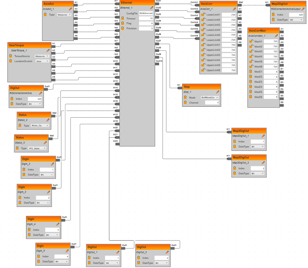
The RSI context (RSIContext.rsix, shown in WorkVisual
below) specifies how RSI is configured, for example what sensor data to send and
to receive from the client.
The screenshot shows the RSI context in Work Visual:
Download this RSIContext.rsix file and copy it
into the C:\Config\User\Common\SensorInterface folder in the Files-tab in
WorkVisual.
The RSI Ethernet XML configuration file
The RSI Ethernet configuration (XML) file specifies which elements are sent/expected over RSI and how they are named.
The only value that has to be adapted from one system to another is IP_NUMBER.
This is the IP of the RTPC of the Intrinsic cluster, to which RSI messages are sent by the KRC (defaults).
Optionally, the xml file can contain descriptions for digital inputs and
outputs (see digital input customization).
Copy the following XML file as RSIEthernetConfig.xml into the same folder
(C:\Config\User\Common\SensorInterface folder in the Files-tab in
WorkVisual.):
<ROOT>
  <CONFIG>
    <!-- IP-number of the external socket, i.e. the Intrinsic cluster -->
    <IP_NUMBER>192.170.10.123</IP_NUMBER>
    <!-- Port-number of the external socket -->
    <PORT>5852</PORT>
    <!-- The name of your system send in <Sen Type="" > -->
    <SENTYPE>Intrinsic</SENTYPE>
    <!-- TRUE means the client doesn't expect answers. Do not send anything to robot -->
    <ONLYSEND>FALSE</ONLYSEND>
  </CONFIG>
  <!-- RSI Data: TYPE=  "BOOL", "STRING", "LONG", "DOUBLE" -->
  <!-- INDX= "INTERNAL" switch on internal read values. Needed by DEF_... -->
  <!-- INDX= "nmb" Input/Output index of RSI-Object of the Ethernet object in RSIContext / Maximum of RSI Channels: 64  -->
  <!-- HOLDON="1", set this output index of RSI Object to the last value  -->
  <!-- DEF_Delay count the late packages and send it back to server  -->
  <!-- DEF_Tech: .T = advance .C = main run / .T1 advance set function generator 1 -->
  <SEND>
    <ELEMENTS>
      <ELEMENT TAG="DEF_Delay" TYPE="LONG" INDX="INTERNAL" />
      <!-- Actual joint positions -->
      <ELEMENT TAG="Pos.A1" TYPE="DOUBLE" INDX="1" />
      <ELEMENT TAG="Pos.A2" TYPE="DOUBLE" INDX="2" />
      <ELEMENT TAG="Pos.A3" TYPE="DOUBLE" INDX="3" />
      <ELEMENT TAG="Pos.A4" TYPE="DOUBLE" INDX="4" />
      <ELEMENT TAG="Pos.A5" TYPE="DOUBLE" INDX="5" />
      <ELEMENT TAG="Pos.A6" TYPE="DOUBLE" INDX="6" />
      <!-- Estimated joint torque -->
      <ELEMENT TAG="Trq.A1" TYPE="DOUBLE" INDX="7" />
      <ELEMENT TAG="Trq.A2" TYPE="DOUBLE" INDX="8" />
      <ELEMENT TAG="Trq.A3" TYPE="DOUBLE" INDX="9" />
      <ELEMENT TAG="Trq.A4" TYPE="DOUBLE" INDX="10" />
      <ELEMENT TAG="Trq.A5" TYPE="DOUBLE" INDX="11" />
      <ELEMENT TAG="Trq.A6" TYPE="DOUBLE" INDX="12" />
      <!-- Status of external sensor (unused) -->
      <ELEMENT TAG="SensorStatus" TYPE="LONG" INDX="13" />
      <!-- Operation mode, e.g. T1 or External -->
      <ELEMENT TAG="ModeOp" TYPE="LONG" INDX="14" />
      <!-- KUKA Ipo State -->
      <ELEMENT TAG="IpoState" TYPE="LONG" INDX="15" />
      <!-- Customizable digital inputs/outputs. Input Tags need to be of format "DigIn.DI<number>",
      where the number needs to be ascending without gaps. Outputs must be similarily tagged
      "DigOut.DO<number>" -->
      <ELEMENT TAG="DigIn.DI1" TYPE="LONG" INDX="16" />
      <ELEMENT TAG="DigIn.DI2" TYPE="LONG" INDX="17" />
      <ELEMENT TAG="DigIn.DI3" TYPE="LONG" INDX="18" />
      <ELEMENT TAG="DigIn.DI4" TYPE="LONG" INDX="19" />
      <ELEMENT TAG="DigOut.DO1" TYPE="LONG" INDX="20" />
      <ELEMENT TAG="DigOut.DO2" TYPE="LONG" INDX="21" />
    </ELEMENTS>
  </SEND>
  <RECEIVE>
    <ELEMENTS>
      <!-- Joint position correction, i.e. joint target position -->
      <ELEMENT TAG="AK.A1" TYPE="DOUBLE" INDX="1" HOLDON="1" />
      <ELEMENT TAG="AK.A2" TYPE="DOUBLE" INDX="2" HOLDON="1" />
      <ELEMENT TAG="AK.A3" TYPE="DOUBLE" INDX="3" HOLDON="1" />
      <ELEMENT TAG="AK.A4" TYPE="DOUBLE" INDX="4" HOLDON="1" />
      <ELEMENT TAG="AK.A5" TYPE="DOUBLE" INDX="5" HOLDON="1" />
      <ELEMENT TAG="AK.A6" TYPE="DOUBLE" INDX="6" HOLDON="1" />
      <!-- Stop the RSI interface on KUKA side -->
      <ELEMENT TAG="STOP" TYPE="BOOL" INDX="7" HOLDON="1" />
      <!-- Customizable digital outputs. Tags need to be of format "DigOut.DO<number>",
      where the number needs to be ascending without gaps. The number of outputs needs to be same
      as outputs in the SEND-section. -->
      <ELEMENT TAG="DigOut.DO1" TYPE="LONG" INDX="8" HOLDON="1" />
      <ELEMENT TAG="DigOut.DO2" TYPE="LONG" INDX="9" HOLDON="1" />
    </ELEMENTS>
  </RECEIVE>
</ROOT>
Customize digital inputs and outputs
By default, 4 digital inputs and 2 digital outputs are configured.
This can be extended to a maximum of 64 inputs and 64 outputs.
Each input must be connected to an input of the Ethernet
object using Bit as the value of DataType field in the RSIContext.
Each output must likewise be connected to an input and and output of the Ethernet
object.
The outputs that are connected to inputs contain the actual values
of an output, not just the set values.
The screenshot of WorkVisual in the RSI context sections shows how those 4 inputs and 2 outputs are set up.
Make sure to map those inputs and outputs to sensible fields in the Mapping
view in WorkVisual as needed for the application (see
WorkVisual section 9.4 "Mapping the bus I/Os").
The hardware module configuration file (see
configuration) must have the same number of
digital_input_names and digital_output_names entries as inputs and outputs
are configured in RSIEthernetConfig.xml.
The names can be freely chosen.
For the 4 inputs and 2 outputs example insert the following lines into the
protobuf configuration file see configuration:
    digital_input_names: ["di_1", "di_2", "di_3", "di_4"]
    digital_output_names: ["do_1", "do_2"]
Those digital inputs can be observed using the
dio_wait_for_input skill.
Digital outputs can be changed using dio_set_output skill.
Additionally, both can be used with the ICON ADIO action.
RSI robot program
The RSI is started from a KUKA KRL robot program. Download this KRL robot
program RSI_MC and copy it to the robot using WorkVisual.
Deploy the changes to the robot
Deploy all changes using WorkVisual onto the robot.
Add the assets in Flowstate
In order to work with KUKA robots in flowstate we have to add their respective assets and
configure them accordingly.
Two components are necessary for a KUKA robot to operate correctly, a KUKA hardware module
and a realtime control service.
The first component, the hardware module, serves as the driver for the robot hardware and
translates KUKA specific commands into an abstract format Flowstate can understand.
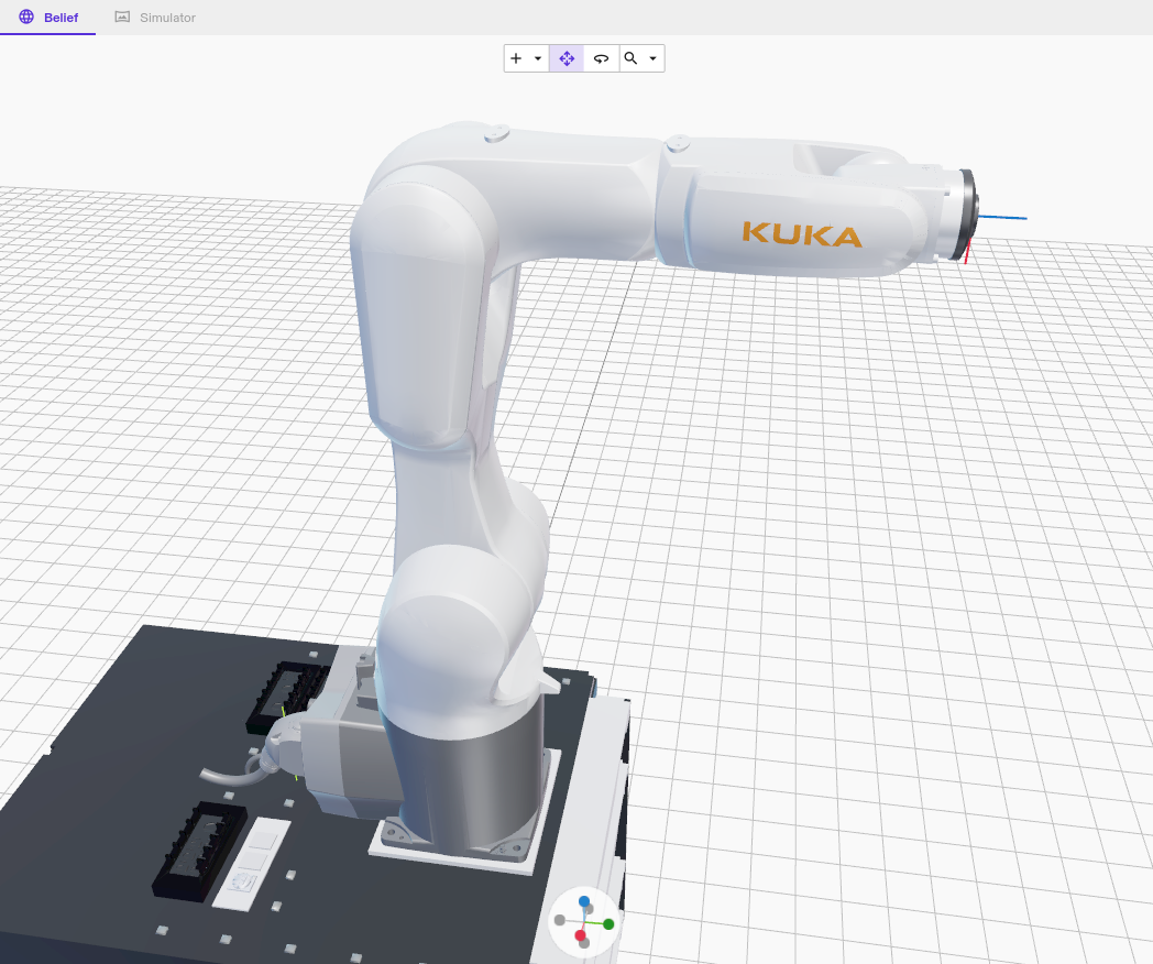
The realtime control service is Intrinsic's main robot controller to visualize various
robot states and provides an entry point for skills to operate.
Deploy KUKA robot assets with geometry information
In case the hardware module is renamed to anything else than robot, the default configuration for the realtime control service is no longer valid.
Follow these instructions to adjust the configurations.
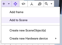
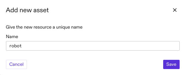
To import the two assets, we have to do the following:
-
Open the Add Asset dialog as shown in the picture.
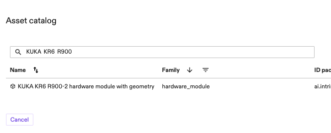
-
Add the KUKA hardware module for your specific robot model.
Importantly, select the asset type that mentions with geometry.
For example to add a "KR6 900" search for KUKA KR6 R900.
Caution: When not using the default namerobot, the corresponding entries in the realtime control service and hardware module configuration need to be adjusted.
-
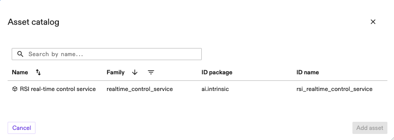
Add the realtime control service which is preconfigured for RSI robots.
For this, open the Add Assets dialog and add the KUKA RSI real-time control service.
Once both resources are deployed, follow the instructions to enable the robot.
(Optional) Modify the local_rsi_host IP
-
Configure the hardware module to use the correct realtime NIC for RSI communication:
-
Select the hardware module instance (by default,
robot) from the tree-view of the Scene, click the Settings tab (at the left side of the Flowstate window) -
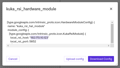
Click Open Configuration File and edit/download its configuration file.
You need to replace the field
local_rsi_hostwith the correct IP of the realtime NIC used by the RTPC in the configuration file. This is the same IP as used in the RSI Ethernet XML configuration. -
Upload/Save the file using the same dialog.
-
-
The resource should automatically Redeploy and apply the new settings.
(Optional) Adjust custom hardware module resource name
In case the hardware module was renamed to anything else than robot, the default configuration for the realtime control service is no longer valid.
Follow these instructions to fix your setup:
To change the configuration, select the realtime control service asset from the scene view, click Settings and from there Open configuration file.
This will display the configuration of the asset.
In there, change the values of hardware_resource_name and world_robot_collection_name to the name of the KUKA hardware module resource.
Enable the robot
When the hardware module has been deployed, it immediately starts listening for the RSI data from the KUKA KRC.
Robot safety training and an introduction to the KUKA robot system is required before executing the following steps!
Follow these steps to enable the RSI using the teach pendant:
-
Release all emergency stops (on the teach pendant, cell etc.)
-
Confirm all messages
-
Switch to automatic mode (physical turn switch)
-
Choose the
RSI_MCprogram from the file view and press the Select button at bottom of the screen (Do not press the Open button since this opens the program for editing)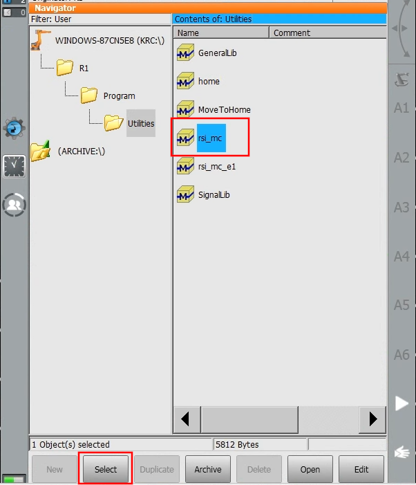
-
Enable the drives (Press the button with
Oat the top. In the dialog pressIand wait until theO-button becomes a greenI-button. If the drives are already enabled, you see a greenIin place of theO.)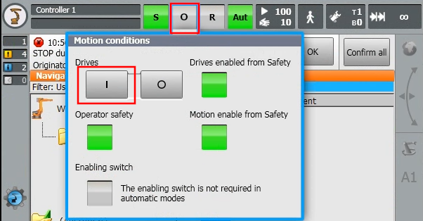
-
Press the green Play button (left of screen) until the cursor arrives at
RSI_MOVECORR()
Now you should be able to move the robot in Flowstate. Potentially, you need to clear remaining faults first in Flowstate.