World concepts
The digital representation of a physical workcell is an important consideration at many different stages during developing a solution. Separate geometric definitions are required for single objects, world editors, runtime world models, and simulation worlds. Depending on the context, you can represent worlds differently in Flowstate to properly interact with them at each level.
Overview
In Flowstate, we represent the runtime geometric relationships between objects in a World. This world (also sometimes referred to as a world model) generally models most geometric properties of all objects. These properties include, but are not limited to, visual and collision meshes, kinematics, and sensor data. Additionally, the world also keeps track of how objects are oriented, or posed relative to other objects.
Each object in the world is a collection of entities, which are typed atoms that make up the world structure. Entities may be any one of a link, joint, frame, or sensor. Each entity is posed relative to its parent entity, and all entities share the world root as their ancestor, forming a tree. Each object, therefore, has a base entity that determines its pose relative to other objects. This base entity's parent will either be an entity in another object, or the root entity. This formulation defines both an entity structure and an object structure for a given world model.
For example, a box object may be represented entirely by a single link
entity:
|
|
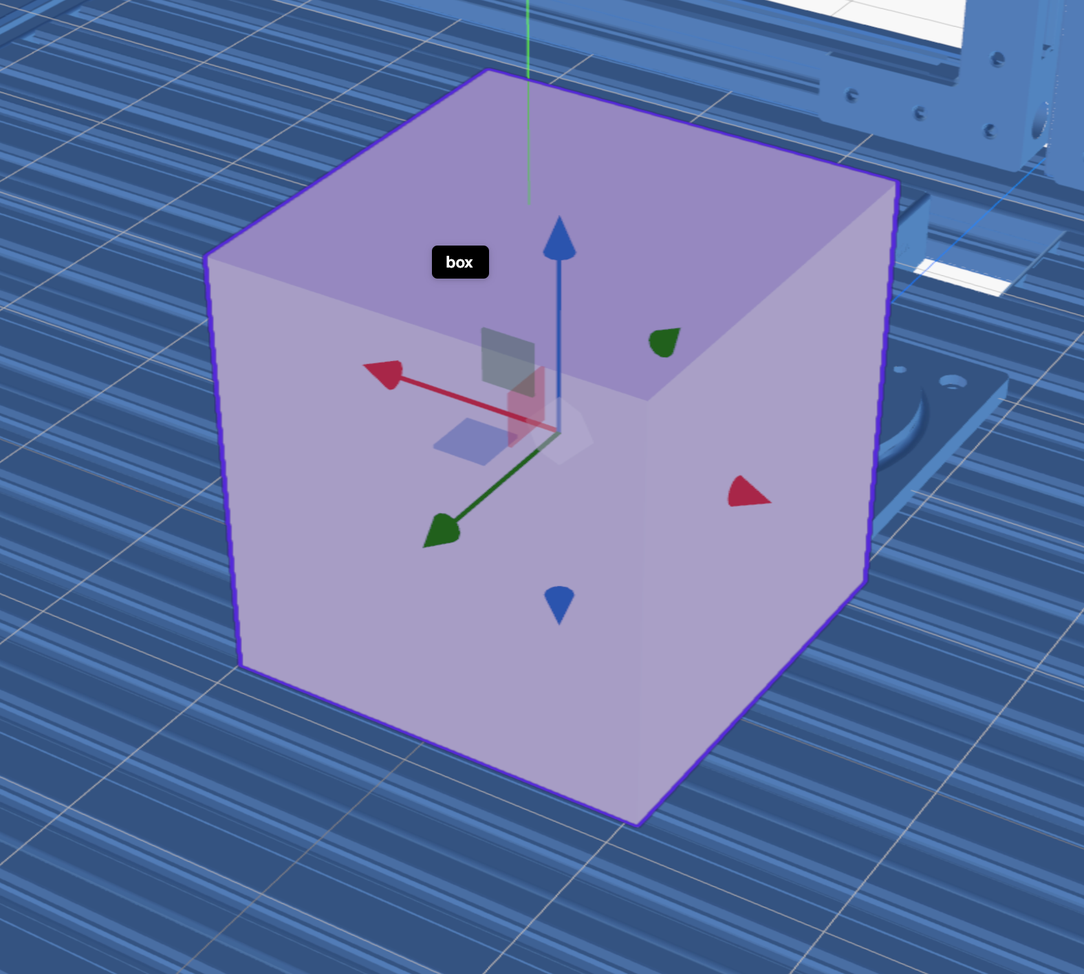

In this example, the parent
object of box is the object that contains the parent entity. The child
entity of link belongs to another object, which is a child object of box.
In the example of a robot with a gripper, we may have a complex heirarchy of entities and objects. In the example that we have a robot with a gripper within an enclosure, this represents a heirarchy of three objects, each with their own internal entity structure:
|
|
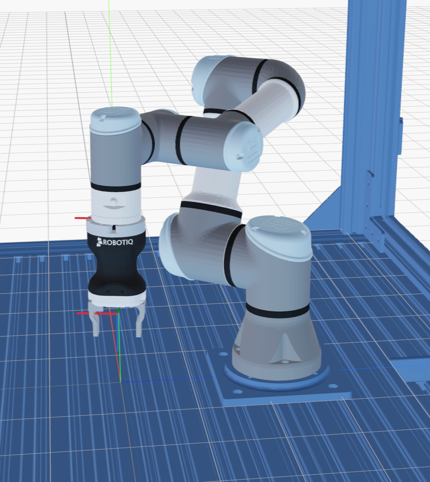

In this example, the enclosure object is a child of the world root (the
enclosure object
is a child of the root object, while the base entity is a child of the root
entity). The robot object is a child of the enclosure, and the gripper
object is a child of the robot object. The entities of the objects are
connected in a way that define a tree of poses
that define their locations within the world model. The relative
poses between these objects is the pose between their base entities.
Entities
Types of entities fall into a number of different categories, each with their own properties and state. Every entity has a pose, and therefore belongs to the tree of poses described in the overview. Some properties, such as geometric meshes, may be defined once at the initialization of the world and model cannot be edited during runtime. Others, such as joint values and pose information, may be edited as a consequence of a running process.
This section describes the variety of different entity types that we support in Flowstate. This is not an exhaustive list and may expand in the future.
Links
Links are the standard geometric building block of worlds. They contain the information about a rigid physical object in the world, and are therefore used to model things like tables, enclosures, and robotic parts.
Links generally contain two types of link-specific properties: geometry and physics. The geometry properties of a link usually define the way that the link is represented as a digital model: visual and collision geometry, which may include triangle meshes or primitives. Geometry is posed internally relative to the entity's pose, and may be scaled to be compatible with the rest of Flowstate. Flowstate uses meters as the internal unit of measurement, so all geometries should be defined in meters.
Physics properties may include information such as center of mass or the inertia matrix. Physics properties are primarily used for simulation, and if they are set improperly we may experience implausible behavior during simulation. For this reason, it is important that we make sure that the collision geometries defined for a link correspond to the physics parameters set.
Joints
Joints represent the connections between links for any object that contains a kinematic system, such as a robotic arm or a two-fingered gripper. Joints are represented by a joint value (the current "position" of the joint) and a set of joint limits which are used by the robotic controllers to manipulate the object (with a few additional properties such as the coefficient of friction for a joint).
Whether or not an object contains joints determines whether or not the object is treated as a kinematic object or not. Kinematic objects generally carry additional object-level properties such as named joint configurations. Joints can be neither the base entity of an object nor can they be the parent entity of a base entity of another object. They are required to have at least one link as a parent and one link as a child. Additionally, dependent joints (joints with multiple parents) are currently unsupported.
Frames
Frames represent named poses that are relevant to solution developers about a given object. The most common example of a frame is the end-effector of a robotic arm, usually labeled as the robot's "flange". Frames are also the only entity that may belong to the root object other than the root entity. Frames carry no additional properties, but may be additionally defined as attachment frames.
Attachment Frames
Attachment frames are special frames that define the pose of their child object. In general, attachment frames usually do not have child entities that belong to the same object. However, when we reparent an object to an attachment frame, the world-space pose of the new object (a.k.a. the pose of the base entity of that object) is defined to be the world-space pose of the attachment frame.
Sensors
Sensors are entities that may define the geometric properties of sensors in the world model. The most common types of sensors are cameras used for perception, which include, for example, the camera intrinsics used by that specific camera. Other examples of sensors may be lidars or force-torque sensors that would be used to detect e.g. placement of objects.
Belief world
The belief world in the context of Flowstate is the world model that corresponds to Flowstate's current understanding of the state of the workcell, whether it's a real workcell or simulated. The belief world can generally be mainuplated from a number of sources during execution, but is most commonly manipulated via skills. For certain classes of objects, like robotic arms, we may be able to update the belief world directly by reading sensor data from the robot controller.
Sensing vs Editing
In general, special consideration needs to be taken when editing the belief world. When we edit the world model representing the current state of the workcell, we are imposing our understanding of the world onto the Flowstate environment instead of sensing it. This may cause inconsistencies, such as whether we can accurately detect whether or not we've gripped an object, which need to be resolved for the accurate functioning of the system.
For this reason, we will often times prefer sensing differences in the belief world rather than editing them directly from the world editor. This surfaces when using the product spawner and the belief world does not match the real (simulated) world. We have to use additional skills to sense the product has entered the workcell so that we can instantiate it in the belief world.
Simulation
During simulation, we have multiple separate world models that we need to maintain:
- The belief world (matching the real workcell scenario)
- The simulated world
- The simulator's internal model of the world
The simulated world is the world model matching the structure of objects and entities that we have described here. This model is generated from the simulator's internal model of the world, and is kept up-to-date during the execution of a process.
We instantiate both of the simulation models from the belief world at the beginning of process execution in order to make sure that our simulator has an up-to-date understanding of the expected initial conditions. However, the simulated world and the belief world differ: the belief world still represents the world model that the Flowstate environment understands the workcell to be in. The simulated world(s) are stand-in replacements for reality that represent the evolution of the physical system represented by the belief world.