Create a pose estimator
During pose estimation, the 6 degree of freedom pose (position and orientation) of an object is estimated based on an acquired camera image. In your solution, you can use this technology to determine the location of an object in your workcell, for example, to manipulate the object or to avoid it during planned moves of the robot.
For some of our advanced algorithms, first a model needs to be learned before you can use this technology in your solution. This is called pose estimation training.
Right now, only rigid body pose estimation is supported.
Creating a new pose estimator
The three main steps to creating a new pose estimator include:
- Configuring and creation using the creation UI
- Fine tuning the runtime parameters in the inference UI
- Deploying the pose estimator to the solution (it can be done from either UI)
'Pose estimator' and 'object detector' are synonymous and may be used interchangeably.
Pose estimators are associated to specific solutions, which means a solution should already be launched.
Prerequisites
- A solution is running
- The workcell contains an (intrinsically calibrated) camera and the object; see adding new objects. Note that depending on the algorithm, you might have to recreate the pose estimator if the intrinsic parameters of the camera change.
Detailed instructions
Launch the solution that you want to add the pose estimator to in Flowstate. Within the Properties panel on the left-hand side, you will find the Pose Estimation panel.
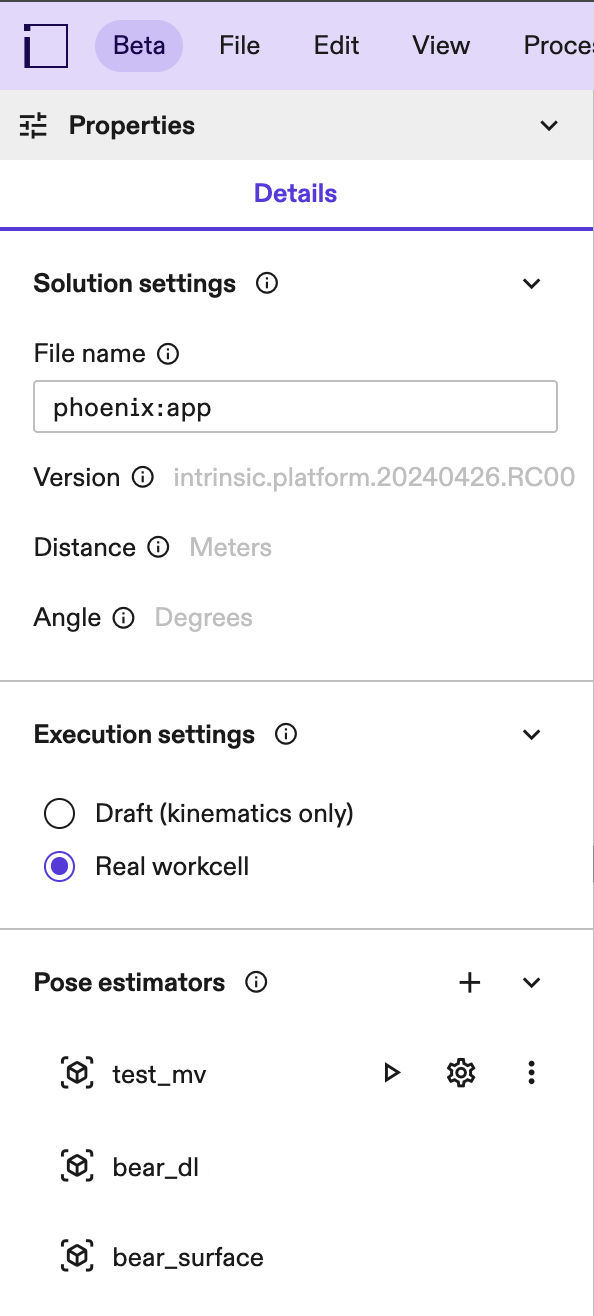
If you cannot see the properties panel, click into an empty space in your workcell (or select the root node in your scene tree).
Click the + button to open the Pose Estimation panel.
Step 1: Setup
Specify the required information for creation:
- Name: A pose estimator is defined by its name. This name is used as a
handle in skills, and shows in the workcell API under
workcell.pose_estimators.<name>. - Object: The object you want to create a pose estimator for. If the object is not yet part of the world, see adding new objects. To modify the object's material properties before creation, see changing material properties.
- Camera: Select a camera to be used for detecting the object. Most pose estimators are fine-tuned to the specific camera intrinsics (and to some degree extrinsics) meaning that once created, it might not be possible to use it with a different camera. If the intrinsic or extrinsic parameters change too much, make sure to calibrate first.
- Pose estimator type: The type of estimator to create. See below for more
information about the advantages and disadvantages of different pose estimators.
- Edge-based: Works best for small pose ranges and objects with clearly visible geometric edges. Training and inference time is fast for small pose ranges, but both grow significantly with an increasing pose range.
- Surface-based: Only available for depth cameras. Works robustly for the whole pose range and trains within minutes. It requires objects with a distinct shape, and texture is not taken into account.
- ML Single-view: A deep learning based pose estimator. Works robustly even for the complete pose range, but requires a GPU for training and inference. Training time is around 3 hours.
- ML Multi-view: A pose estimator based on deep learning accurately determines poses using two or more calibrated cameras with overlapping fields of view. During inference, it's critical that all cameras used have similar intrinsic parameters to the one selected during training, that is, the same image sensor, resolution and lens type as the camera specified during training. This method performs reliably across a wide range of poses and in cluttered environments. However, it necessitates a GPU for both training and inference processes. The training duration typically spans 3-4 hours.
- One Shot: A pose estimator based that leverages foundation models to accurately determines poses using two or more calibrated cameras with overlapping fields of view. It differs from the ML Multi-view type primarly in its creation time and inference speed (see section below). During inference, it's critical that all cameras used have intrinsic parameters similar to the camera selected during creation. This means they must share the same image sensor, resolution and lens type as the camera specified during creation. To create a One shot pose estimator, your organization needs to have access to a "One Shot Base Model". In case your organization has installation rights, you can install this asset from the Assets Catalog to your solution. Once installed the creation dialog will display the option to create a one shot pose estimator. We provide different types of One Shot Base Models (e.g flat parts, primitives, 3D parts) based on the user's application requirements. This type of pose estimator performs reliably across a wide range of poses mainly with singulated objects.
To use ML Single-view and ML Multi-view pose estimators, your organization needs to enable training because the required hardware is expensive.
It's important to have a rough intrinsic or extrinsic calibration and a good object placement in the world before creating a pose estimator.
We recommend using reasonably sized / decimated CAD models for creating pose estimators, CAD models larger than 15 MB may cause creation errors for certain pose estimator types.
Choose the right pose estimator type
Choose the right pose estimator type depending on the kind of object you want to detect, the available camera hardware and your creation time and inference requirements. This section gives an overview of the requirements, advantages and disadvantages of the different pose estimator types.
| Edge-based | Surface-based | ML Single-view | ML Multi-view | One-Shot | |
|---|---|---|---|---|---|
| Supported camera types | RGB | Depth. Requires a dense point cloud to detect the object, so make sure the lightning conditions of your workcell are suitable for the chosen depth sensor (e.g. some structured light depth cameras struggle with sunlight). | RGB | RGB | RGB |
| Compute hardware requirements | CPU | CPU | GPU. Required for training. If not available for inference, expect long latencies. | GPU. Required for training. If not available for inference, expect long latencies. | CPU for creation. GPU for inference, if not available expect long latencies. |
| Recommended objects | Relatively simple CADs (under 100k edges) with clear edges. | Objects with distinct geometries (a distinct 3D shape). Texture is not taken into account. Does not work well with flat/thin objects, or when small parts of the object are visible - like a box where only one side is visible. The algorithm requires a dense point cloud, so make sure the selected depth camera provides that for the object (usually not the case for transparent, black or highly reflective objects). | Can handle a variety of objects,but the geometry needs to have materials with realistic properties in order to transfer to the real world (see changing material properties). | Can handle a variety of objects, but the geometry needs to have materials with realistic properties in order to transfer to the real world (see changing material properties). | Can handle a variety of objects, but the correct "One Shot Base Model" needs to be chosen based on the specifics of the application. We provide different "One Shot Base Models" for different objects (e.g Flat Parts, primitives, 3D parts), use the one more representative for the target object. |
| Accurate object material needed | No | No | Yes | Yes | Surface textures (e.g mirror-like, rough, plastic) of the object can be important and can improve the model accuracy if properly defined. Badly modeled object textures can lead to worse performances. In case of purely metallic objects no texture/color is necessary. |
| Recommended pose range | Highly constrained. Optimally select a few poses on the icosahedron representation. | Unconstrained | Unconstrained | Unconstrained | Unconstrained but accurately defined and restricted pose range drastically reduces creation and inference time. |
| Environment | Little clutter | Can be cluttered, but the object's shape should be distinct from the background. E.g. when estimating a box on a flat surface, all three sides of the box need to be visible to distinguish it from the background. | No issues with clutter. Object should be visually distinct from the background. | No issues with clutter. Object need not be visually distinct from the background. Objects can be occluded in some of the camera views used for detection. | Works reliably for singulated objects and not recommented for cluttered environments. |
| Creation time | Within a few minutes (for the recommended pose range and object types). Grows exponentially with increasing pose range and object complexity. If the object is very close the camera, training time can increase significantly. | Within a few minutes | Within a few hours | Within a few hours | Within a few minutes based on pose range and symmetries |
| Inference time | Seconds (for the recommended pose range and object types, and little clutter in the environment) | Seconds | Seconds (with a GPU) | Seconds (with a GPU) | Seconds (with a GPU) |
Surface based pose estimator examples
| Works well. | Does not work well. |
|---|---|
The surface-based pose estimator works well on discriminative objects that expose many different normal directions.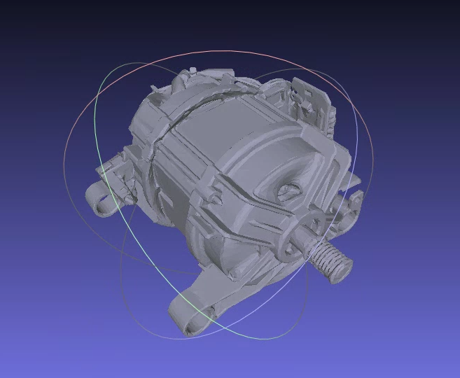 | The surface-based estimator has weaknesses with flat surfaces where similar objects can be found anywhere in human environments (since detecting their poses is ambiguous).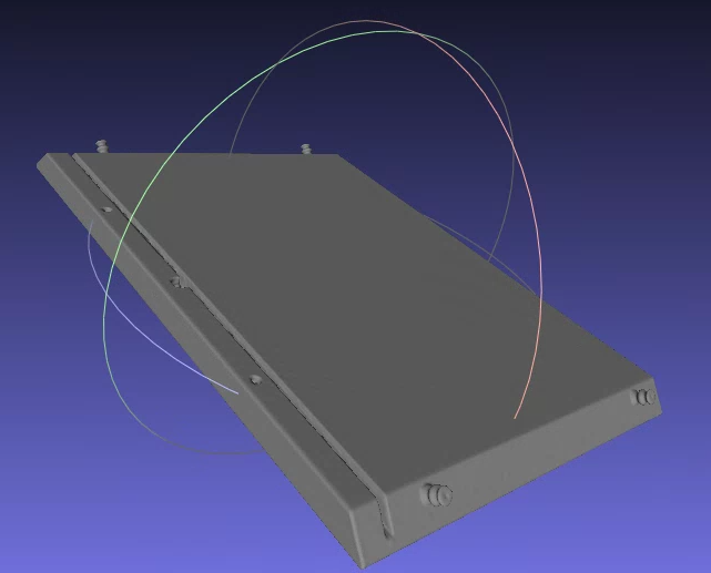 |
The surface pose estimator also doesn't make use of texture - therefore additional texture information doesn't help to make the results more stable, robust or reliable.
Step 2: Defining symmetries
If an object contains a symmetry, it means that the visual appearance of an object is the same from different angles. Since those pose redundancies that the pose estimator does not need to learn, you should specify the symmetries of the object.
Examples for symmetries
| Example | Symmetries |
|---|---|
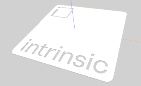 | No symmetries. |
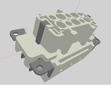 | No symmetries. While this looks like a symmetry around the z-axis about 180deg at a first glance, it is not - the connector has two pins on one side, but only one pin on the other side. |
 | - Symmetry 1: Finite symmetry: Axis: x-axis (red) & Angle: 180° |
 | - Symmetry 1: Finite symmetry: Axis: x-axis (red) & Angle: 180° - Symmetry 2: Finite symmetry: Axis: y-axis (green) & Angle: 180° - Symmetry 3: Finite symmetry: Axis: z-axis (blue) & Angle: 180° |
 | - Symmetry 1: Revolutional symmetry: Axis: y-axis (green). - Symmetry 2: Finite symmetry: Axis: z-axis (blue) & Angle: 180°. |
Step 3: Defining the pose range
During this step, you can define the pose range you want to create the pose estimator on. Depending on your use case, you might want to limit the views your estimator recognizes the object from, maybe because you can only pick a part in a specific orientation. Depending on the type of pose estimator, you might also need to limit the pose range to reduce creation and inference time. For example, for edge-based pose estimation, it is critical to limit the range as much as possible. In particular, the minimal distance to the camera as well as the number of camera views have high impact on the creation time and reduces the detection accuracy.
Different ways are supported to specify the pose range, for more information see the following sections. For all view spaces, you can also set the minimum and maximum distance at which the object should be recognized at. Make sure these values cover the minimum and maximum distance your object appears in. Make sure the distances are set up such the object is not too close and not too far away in the image (rough guidelines: the object should cover at least 75x75 pixels, but not more than 50% of the image).
The initial parameters are set based on the selected object's and camera's location in the world, and the default values are set based on the selected pose estimator type, thus providing you with a sensible default setting for your workcell setup.
Hemisphere
Choose a whole hemisphere for the view space the pose estimator is created on. Hemispheres can be selected along each axis of the object's origin, or the whole sphere can be selected to create the pose estimator on the whole view space.
Latitude-Longitude
From a given reference position of the object, the pose range can be specified using angles along the latitude and longitude of the sphere.
Icosahedron
They are described by an icosahedron approximating a sphere whose selected vertices represent possible poses (or camera views) onto the target object. In detail, the following interactions are possible to select camera views:
- The minimum and maximum distances from the camera views to the target object center can be specified in the text boxes. Note that the minimum distance can have high influence on the creation time if set too low, for example if the projected object fills large portions of the image.
- Middle-clicking and moving the mouse rotates around the object. The same can be achieved by holding the left control key while left clicking and moving the mouse.
- Right clicking and moving the mouse moves towards or away from the object. The same can be achieved by the mouse wheel.
- A left-click a vertex selects or deselects its associated camera view.
- Left clicking outside a vertex and dragging over deselected vertices selects them.
- In the top right corner, clicking on one of the buttons selects or deselects all vertices and their associated camera views or resets the interactive camera to its current pose in the workcell.
Examples for problematic pose ranges
| Example | What is the problem? | How to solve it |
|---|---|---|
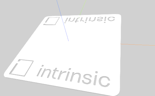
Flat object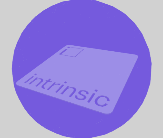 | Some of the poses in this full hemisphere pose range view the flat object from its thin side. This can lead to misdetections or hallucinations by the pose estimator, as such simple shapes are commonly found in human environments. One problematic view: 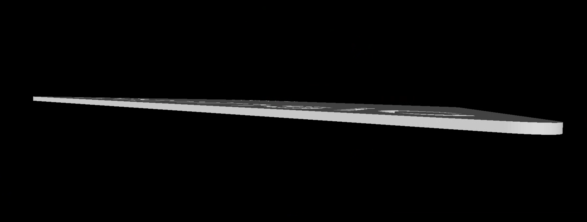 | Use the icosahedron pose range and select all poses that do not have the aformentioned problem. 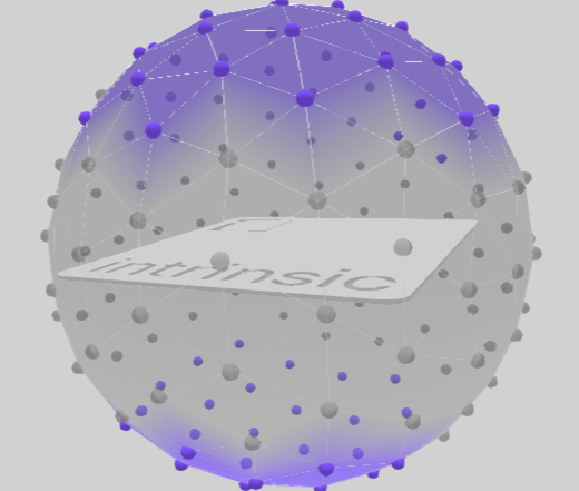 |
Primitives visible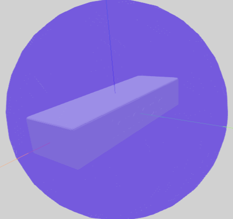 | The object looks like a primitive (in this case a rectangle) from some views in the pose range. Primitives are simple shapes that appear frequently in human made environments, especially industrial environments, such as lines, circles, rectangles, etc. One problematic view (left) and hallucinated detections after creation (right): 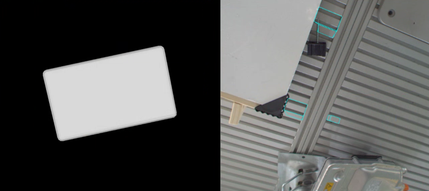 | Use the icosahedron and do not include the pose from which the object looks like a primitive. |
Large distance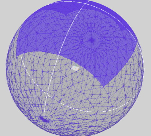 | Some views in the pose range see too little surface area of the object to detect it. While the object might still be detected, seeing very few pixels that cover the object decreases accuracy of the pose estimator. | Decrease the maximum distance in the pose range if possible. |
Small distance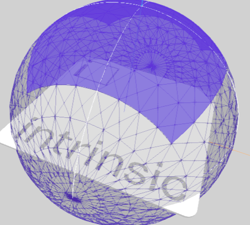 | The object is cut off in some views:  | Increase the minimum distance in the pose range. |
Step 4: Creation parameters
This section contains creation parameters specific to a particular pose estimator. They are usually set to sensible default and don't need to be changed.
As the name suggests, these parameters affect the creation process; changing a creation parameter requires creating the pose estimator again.
Step 5: Creation progress
On the last step you can check the creation progress of your pose estimator. Note that depending on the type of pose estimator and the parameters you selected, creation can take quite a while. You can close the UI in the meantime.
Once creation completed successfully, you can click the Open inference button to test your pose estimator live on a camera of your choice. See also documentation on the inference UI.
Or you can click the Save button to deploy the pose estimator directly to your solution. After deploying, the pose estimator is available to use in skills.