Intrinsic Plenoptic System (IPS)
General Description
The Intrinsic Plenoptic System (IPS) is a multi camera system that can produce various signals (intensity, depth, polarization). It is particularly suitable for industrial vision applications like bin picking, assembly, or inspection. IPS can be optimally employed as a camera asset in Flowstate, in conjunction with pose estimation or point cloud generation.
IPS integrates multiple cameras in a stereo camera array with multiple on-board vision chips and advanced image signal processing. The on-board vision subsystem utilizes vision processing units and provides peripheral and serial device interfaces for data transfer and control of on-board sensors.
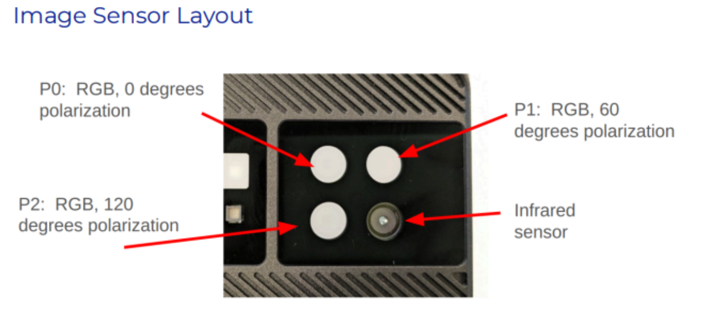
Each unit consists of a 2x2 sensor array, with each array sampling the scene in both RGB, which includes three linear polarization angles, and infrared. In addition to the sensors, IPS also includes a visible light (RGB) flash, NIR flash, polarized visible light flash, and an IR dot projector, all capable of independent triggering and synchronous operation with the on-board sensors. The plenoptic sampling provided by IPS therefore includes multiple viewpoints, multiple spectra (visible + infrared), and multiple modalities (polarized and unpolarized light). Each unit is calibrated in the factory and all calibration parameters are stored in on-board memory.
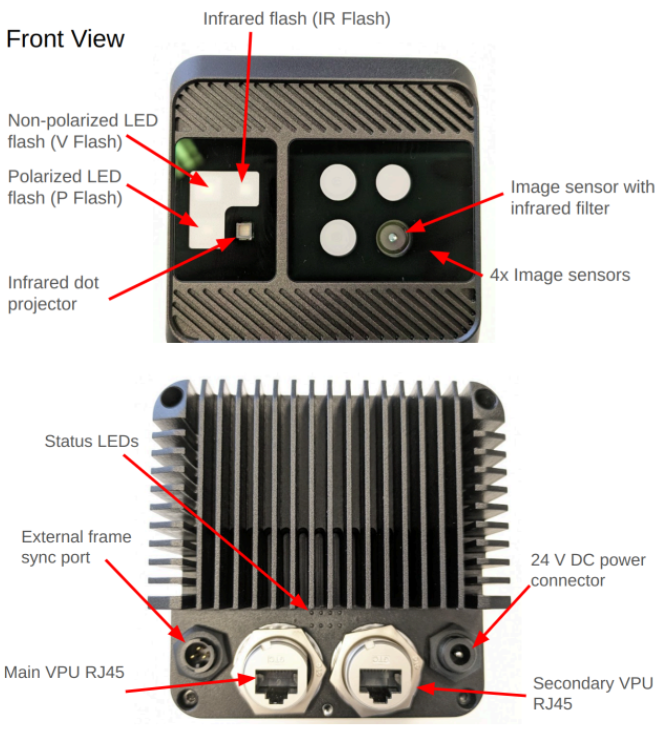
IPS sensors and active illuminators
The vision chips contain MIPI interfaces and on-board ISP pipelines that enable direct processing of up to 4 high resolution sensors, with support for up to 700 million pixels per second of image signal processing throughput.
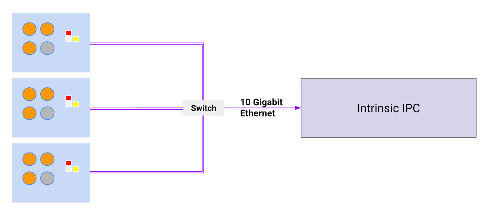
The external interface for data uses two 2.5 Gb Ethernet interfaces with PoE, enabling a high frame rate data capture and power delivery. The cameras are connected to an Intrinsic configured IPC that runs Intrinsic OS and executes pose estimation and point cloud generation algorithms.
An IPS system
The multiple spectral camera approach allows for the potential estimation of various physical properties such as shape, texture, and material reflectance, which can help with improving the robustness of the estimated pose of objects.
Use Cases
The IPS is designed for best-in-class industrial machine vision, prioritizing lighting invariance, material invariance and system robustness. The system is meant to be used in industrial settings in conjunction with a robot. Both, robot and IPS are controlled via Flowstate.
Some of the use cases include:
- Structured bin picking - e.g. boxes on a pallet
- Semi-structured bin picking - e.g. injection molded plastic composite parts in a bin with clear partitions
- Unstructured bin picking - e.g. fasteners in a box that need to be picked
- Assembly - e.g. take fastener from a bin and place it in a precise location for a torque controlled wrench to finish assembly of two sub assemblies
- Inspection - e.g. quality inspection of assembly quality by judging pose of sub assembly in a final assembly
This system can serve industries such as manufacturing, logistics, material handling in machine shops, and machine building.
The IPS is available in two SKUs with distinct working volumes: SKU1 is optimized for a 2.5m working distance, while SKU2 is tailored for 1m. The cameras are meant to be handled by a skilled workforce in a manufacturing plant with minimal training. The setup and operating instructions are provided as a part of Intrinsic Flowstate.
Features and Specifications
System Features
- 6DOF pose estimation
- Collision avoidance point clouds
- Polarization enhanced edge detection
- Spectral, multi modal sampling
Specifications
| Specification | Value |
|---|---|
| Operating temperature | 0-40 deg C |
| Storage | Max 65 deg C at 93% humidity; Min -20 deg C |
| Vibration | up to 5G from 10-500 Hz |
| Shock | 15G |
| Lighting | 50-200,000 Lux |
| Compliance | FCC, CE, REACH and ROHS compliance pending |
| Weight | 1.0 Kg (preliminary) |
| Enclosure | IP65 rated |
| Max Power | 30W |
| Ethernet cable type | Cat 6 minimum |
| Max cable length to next ethernet device | 50 m |
| PTP-IP (Precision Time Protocol Industrial Profile) | L3E2E |
| Interfaces | 2x 2.5 Gb Ethernet ports for data transfer and camera control 1x PoE port IEEE 1588 PTP synchronization Hardware synchronization with non-PTP devices 24V DC power |
| Scanning FOV | 1.39 m x 1.04 m at 1.5 m distance 1.85 m x 1.39 m at 2.0 m distance 2.77 m x 2.08 m at 3.0 m distance SKU1 designed for 1.5 - 3.0 m working distance (IPS2-Quad-3C-12MP-1R-5MP-2000) SKU2 designed for 0.85 -1.35 m working distance (IPS2-Quad-2C-12MR-2R-5MP-1000) |
| PTP-IP (Precision Time Protocol Industrial Profile) | L3E2E |
| API | Supported in Flowstate along with ROS2 interface |
Sensors and components
| Component | Value |
|---|---|
| 50MP, Omnivision RGB sensor used in binned mode (OV50D-2C) | 12.58MP effective resolution 1.224 x 1.224 µm pixels RGB Bayer Effective resolution: 4096x3072 10-bit RAW RGB with high QE in 850/940 nm 10-bit ADC MIPI CSI-2 (2.4 Gbps/ lane x 4) Image acquisition time: 30 ms (HDR off) and 500 ms (HDR on) |
| 5 MP, Omnivision Near-IR sensor (OX05B1S) | Effective resolution: 2560x1920 Image acquisition time: 30 ms (HDR off) and 500 ms (HDR on) |
| Flash | 1x RGB flash with up to 20 lux at 2.5m distance 1x IR flash with up to 20 lux at 2.5m distance |
| Dot Projector | Custom pattern at 940 nm 60K dots CLASS 1 LASER PRODUCT |
| Lens | Custom lens design for industrial imaging |
| RGB Sensor | 4096 x 3072, 1.224 micron pixels |
| RGB Optics | DFOV / HFOV / VFOV - [61.1 / 50.6 / 39.0] Focal Length - 5.38 mm F# - 2.2 |
| IR Sensor | 2592 x 1944, 2.2 micron pixels |
| IR Optics | DFOV / HFOV / VFOV - [60.0 / 49.6 / 38.2] Focal Length - 6.32 mm F# - 2.59 |
| Vision Chip | Intel® Movidius™ Myriad™ X for ISP and edge compute Up to 4 HD resolution RGB cameras Stereo depth accelerator 700 million pixels per second of ISP 4 TOPS (with 2.5 MB on chip memory) |
Camera Field of View
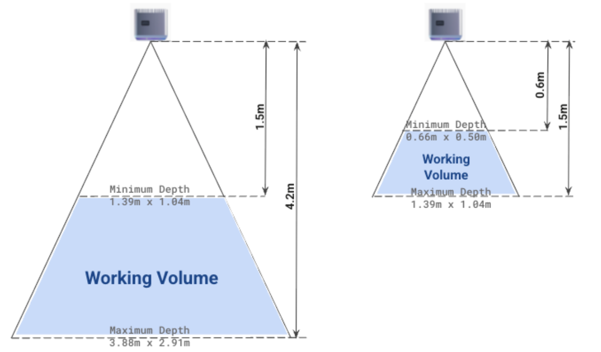 Left showing the camera field of view for IPS SKU1 and right showing the field of view for IPS SKU2
Installation Instructions
Mounting IPS units
The IPS system has five mounting holes on the bottom as shown in the image below.
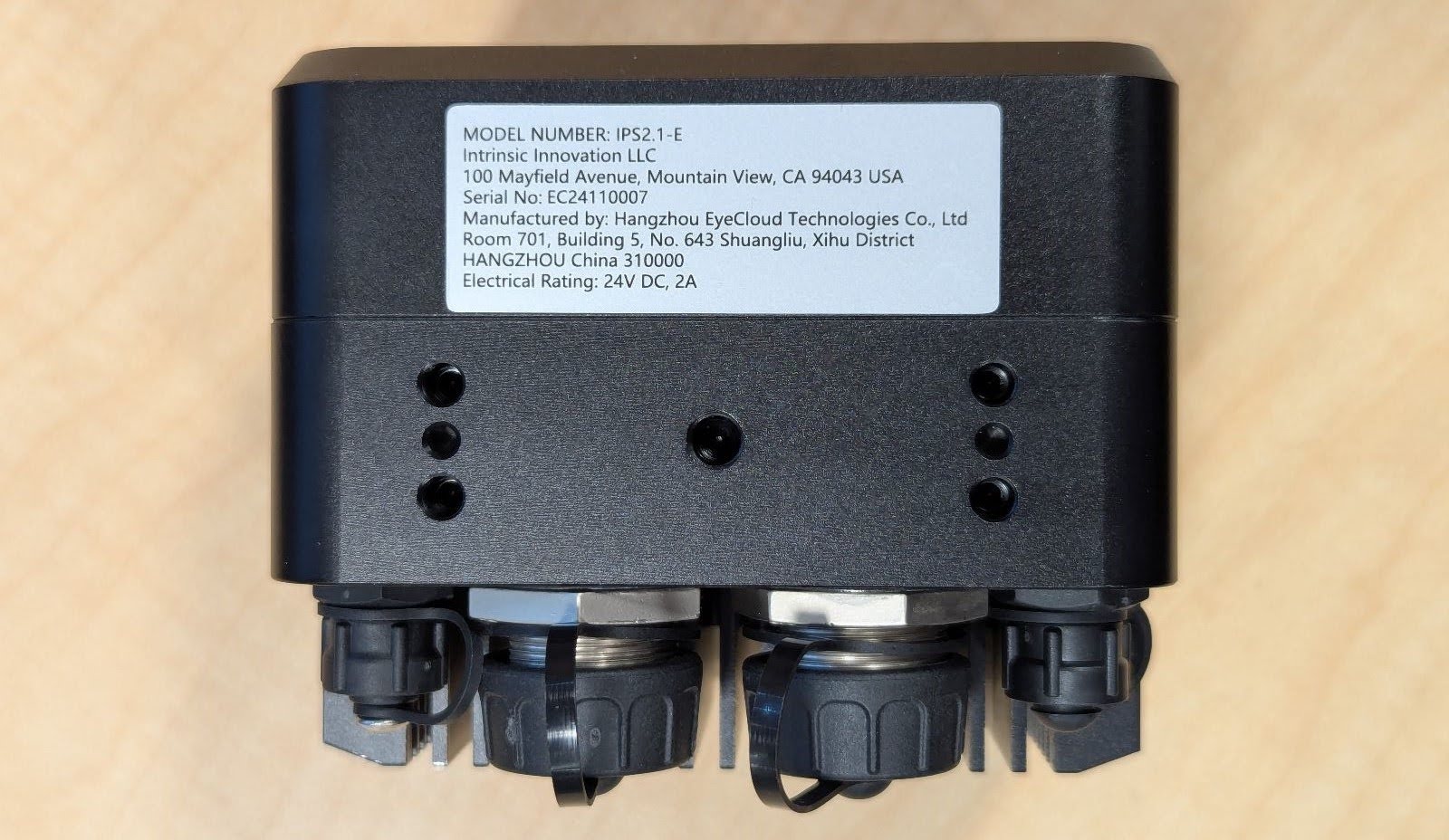
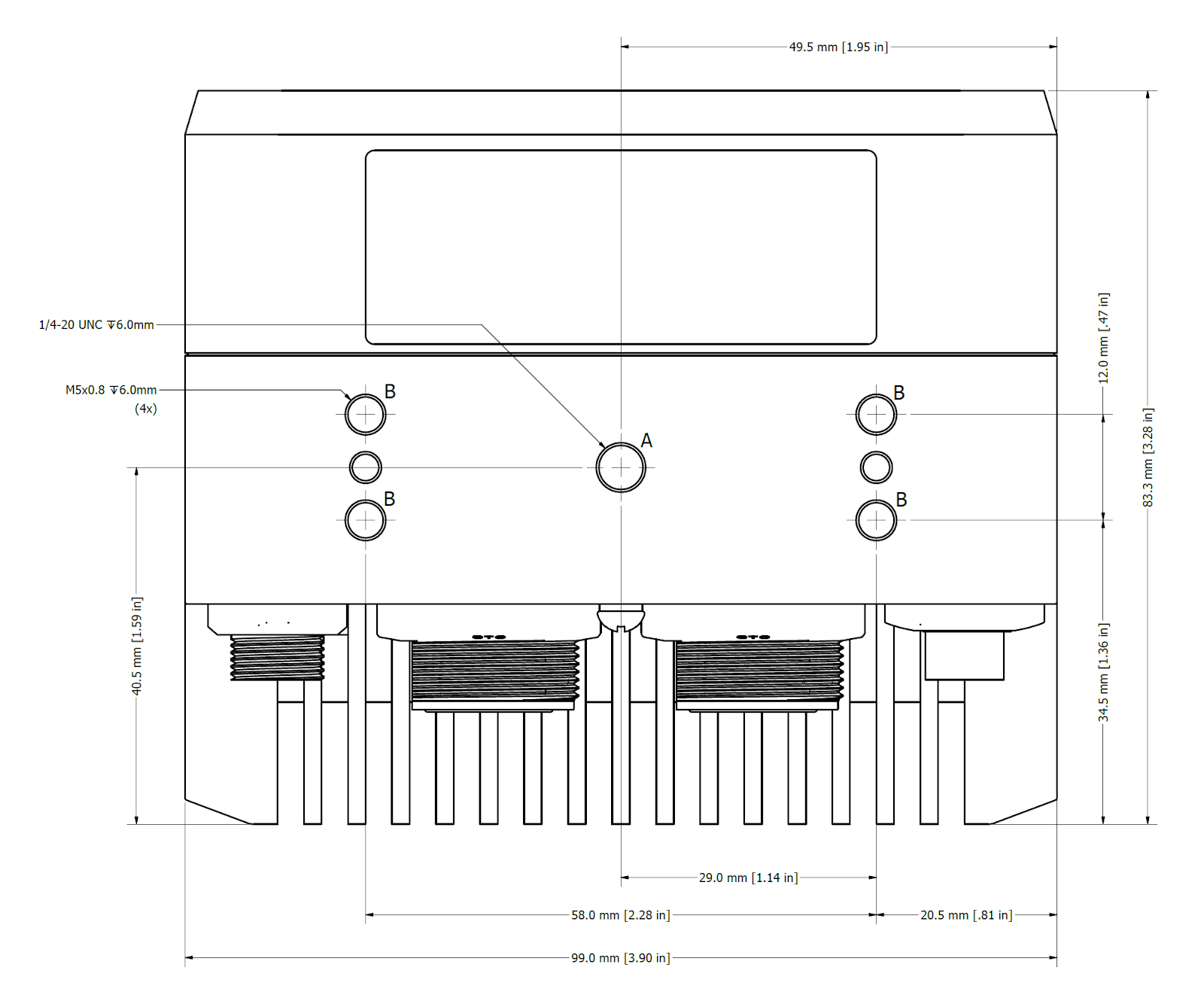
- Center hole (A) has a 1/4-20 UNC thread that is commonly used for camera tripods.
- Four outer holes (B) are M5 x 0.8
- Thread depth is 6 mm (~15/64 inch). Do not insert longer screws or you may damage the unit.
- The fastening torque is 6 Nm on the M5 screws and 9 ft lbs / 12.2 Nm on the center screws. Use steel grade 10 or above for screws. Do not exceed the torque or you may damage the unit.
- For situations where vibrations may occur, we recommend using Loctite 222 or a similar threadlocking adhesive.
- Do not use the single center screw for overhead mounts. In situations where people can be below the camera only use the four outer mounting holes to ensure redundancy and avoid injuries from cameras falling down.
- To ensure best results the cameras should not move after calibration, especially relative to each other if multiple units are used. Therefore it is important to mount a multiple camera setup onto the same rigid structure.
Mounting examples
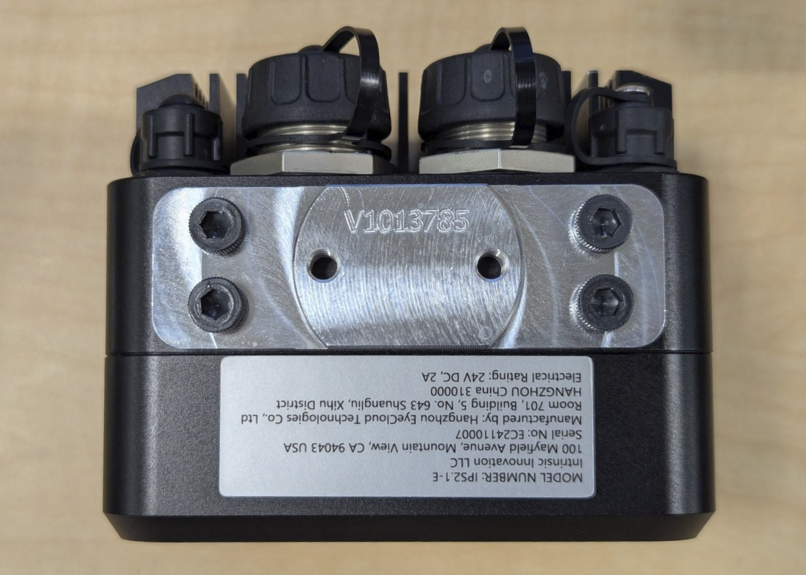
- Attachment to a custom mounting plate with the (4x) Outer screws. In this case a 6MM thick aluminum plate was used with M5x0.8, 12MM Long Socket Head Cap Screws. This plate was then attached to a rigid aluminum profile structure.
- After successful installation of the hardware, follow the instructions to connect the camera and set it up in Intrinsic Flowstate.
Connecting IPS units
To power and connect to the IPS units, a 10 Gb PoE++ network switch is recommended. Specifically, we recommend the Netgear MS510TXUP smart switch. If waterproofing is required, connect ethernet cables which screw into the unit's connector threads, otherwise standard Cat6 cables will suffice.
The switch must be configured to PoE++ mode to support the power demands of the device. In addition, the switch MTU should be set to 9216.
The host IPC interface connected to this switch should have it's MTU size set to 9000. This can be configured by using the Flowstate IPC management interface. To do so, find the entry with the desired IPC, press the menu button, and then press Configure network. In the dialog that opens up, select the appropriate network interface, expand the Advanced panel, and finally set the MTU input to 9000.
Follow the ROS/IPS specific instructions on how to connect the camera.