Set up a robot with Flowstate
This documentation guides you through setting up a robot and other real-time hardware with Flowstate.
The steps for adding assets to Flowstate always follow the same pattern and are described below. For guides on configuring assets for specific hardware connecting robot hardware, see the sub-pages of this section.
Add a robot to Flowstate
To use robots with Flowstate, you must add a real-time control service and a specific hardware module driver for the robot type, (e.g., the FANUC StreamMotion hardware module driver for FANUC robots) to Flowstate.
The hardware module driver serves as an abstraction layer between the specific communication protocol and the interfaces of the real-time control framework of Flowstate.
The real-time control service is home to all real-time controllers in Flowstate and manages and controls all connected hardware under real-time constraints. One real-time control service can communicate with multiple hardware module drivers, while a hardware module can only be controlled by a single real-time control service
Assets tagged with HardwareDevice bundle a geometric asset and a hardware module driver service into a single asset. This guide is for such HardwareDevices.
Fieldbus hardware module driver assets usually do not contain geometries. In case they need to be represented by a geometry, you need to add an extra geometry asset for it.
For a guide on adding custom kinematics visit: Install custom robot kinematics
To import the two assets, you have to do the following:
-
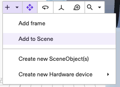
To add the robot geometry and the robot hardware module driver, open the Add to Scene dialog.
-
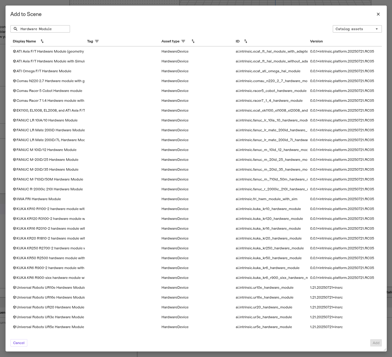
Next, add the hardware module driver for your specific robot model. For example to add a "Universal Robots UR5e" search for UR5e.
- FANUC LR Mate 200iD/7L
- KUKA KR10
- Universal Robots UR5e
- Type
fanucin the search box. - Select the
FANUC LR Mate 200iD/7L Hardware Moduleand click the Add button.
- Type
kukain the search box. - Select the
KUKA KR10 R1100-2 hardware moduleand click the Add button.
- Type
universalin the search box. - Select the
Universal Robots UR5e Hardware Moduleand click the Add button.
-
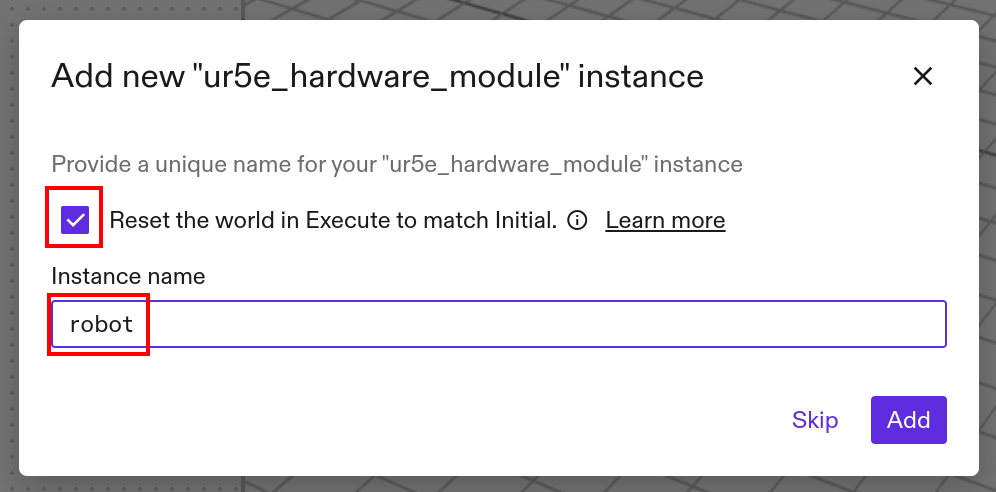
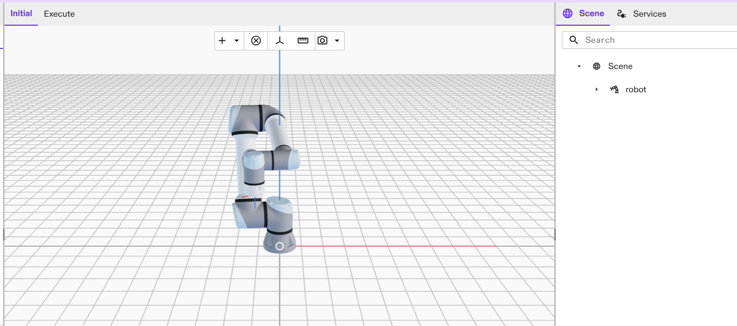
You'll be presented with the following screen. Verify that the unique instance name is called "robot" and select it to add to the scene. Also select "Reset the world to in Execute to match Initial". This is important since the real-time control service takes the configuration from the "Execute" world. In case your forgot to tick this checkbox, you can click Reset to initial in the Execute tab of the 3D scene view.
-
Navigate to the Services tab on the right side of Flowstate Editor and open the Add service dialog.

-
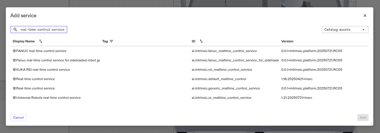
Add the real-time control service, ideally the one that is preconfigured for your robot manufacturer.
- FANUC
- KUKA
- UR
- Select the
FANUC real-time control serviceand click the Add button.
- Select the
KUKA RSI real-time control serviceand click the Add button.
- Select the
Universal Robots real-time control serviceand click the Add button.
-
You may choose any name in the following dialog; however, using a consistent name is recommended to maintain cross-compatibility for behavior trees across your solutions e.g.
robot_controller. Click Apply to add the service to the solution.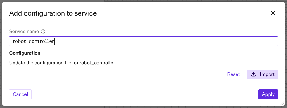
It is also possible to use a custom name, but this requires several configuration changes in the real-time control service and in the hardware module driver configuration. Expand this section to learn more.
If you wish to provide a custom name for the hardware module instance created in Step 3, you must configure the service in code. To do this, open its configuration by selecting the service in the Services tab on the right side. Then navigate on the left side to Config -> ... -> Open in Dialog -> Code.
The dialog should look similar to the picture:
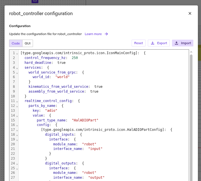 .
.
Replace in the following entries the "robot" value with your chosen name of the hardware module driver instance.
hardware_module_names: "robot"hardware_module_that_drives_clock: "robot"(not necessary for all setups)- All occurrences of
module_name: "robot"
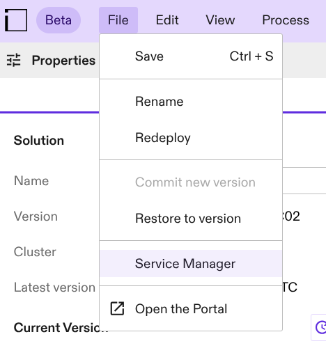
Click Apply to save the changes. Then navigate to File -> Service Manager and toggle the Enable/Disable switch of the real-time control service and wait for a few seconds. You might need to repeat this step a few times until the changes have been propagated.
Now the robot geometry, the hardware module driver and real-time control service have been added to your Flowstate solution.
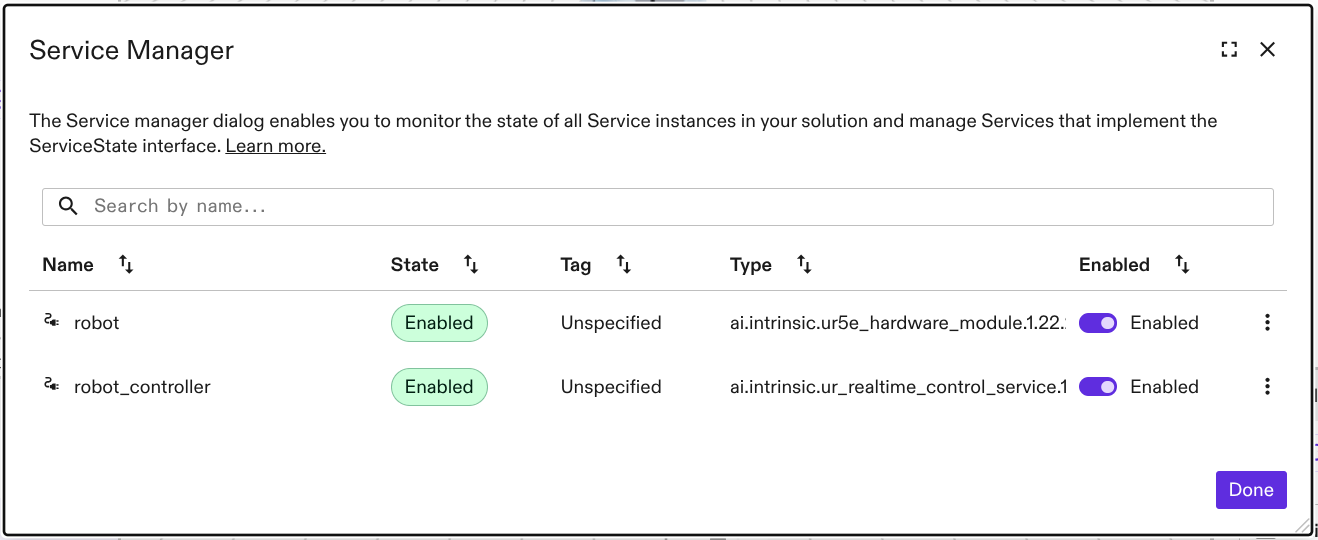
Enable the robot
Once the robot and the control service is added, you need to make sure the robot and the real-time service are connected. The Service Manager UI shows the current state of the running services.
- In simulation mode, the robot and the control services should directly be enabled.
- On real hardware, services typically require initial configuration. Be prepared for runtime or configuration errors to appear in the Service Manager UI after adding a service until the necessary parameters are set. For help on the robot manufacturer specific configuration, check their specific sub-pages of this documentation page.
Select File → Service Manager.
Non-persistent errors can be cleared by clicking the Enabled switch on the robot_controller.
This will also clear faults on the robot service if its correctly connected to the robot_controller.
If you followed the instructions above, this should be the case.
For more information about specific robot manufacturer specific hardware module drivers, check their specific sub-pages of this documentation page.