EtherCAT setup
Flowstate offers full Class A EtherCAT MainDevice functionality. It interacts with a variety of EtherCAT hardware, such as digital input-output bus couplers or force-torque sensors. This page describes how to setup EtherCAT in Flowstate. In case of issues, consult the diagnosis and troubleshooting site.
Overview
EtherCAT support in Flowstate is provided through the realtime control framework service in combination with the EtherCAT hardware module. The setup consists of 5 main steps:
- Configuring the RTPC's network interface
- Configuring the EtherCAT bus topology, sync managers and PDOs (process data objects)
- Adding and configuring the EtherCAT hardware module
- Adding potentially required geometric objects, such as force-torque sensors, to the scene
- Configuring the realtime control framework service
To simplify the setup of force-torque sensors, Flowstate provides ready-to-use Scene Objects for the ATI Axia 80 and ATI Omega 191 force-torque sensors. Follow Preconfigured force-torque sensor setup to find simplified setup instructions below. Alternatively, start with Configuring the RTPC for step-by-step instructions.
Step 1: Configuring the RTPC
Please follow the Connect an industrial PC guide to connect the RTPC to the EtherCAT devices.
Step 2: Configuring the EtherCAT bus topology
Flowstate does not currently provide a user interface for EtherCAT bus scanning or topology configuration (including sync managers and PDOs). We recommend using the integrated EC-Engineer Web, which can run in parallel with Flowstate to generate an ENI file (EtherCAT Network Information). Alternatively, you can also use tools such as TwinCAT (tutorial), or EC-Engineer. With the ENI file proceed with the next section. Alternatively, you can start with one of the example configurations provided below.
Step 3: Adding and configuring the EtherCAT hardware module
Adding the module
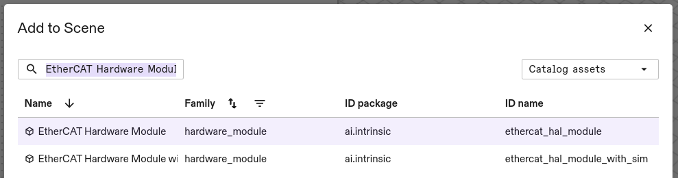
The EtherCAT hardware module is available through the assets catalog. Select the Services tab on the right and then Add service to open the corresponding dialog.

Look or search for EtherCAT hardware module and select the one with the ID ethercat_hal_module.
The next dialog window asks for a name for your EtherCAT hardware module instance. Select a name of your choice, i.e. ethercat and proceed. The module is now being deployed and will be available shortly.
Once it is deployed, you find the module in the Services tab on the right. Note, that you might have to switch the tabs for the view to be updated.

Configuring the module
In order to configure the module, select it in under Services and then select Manage configuration in the Settings tab on the left side of the Flowstate window.
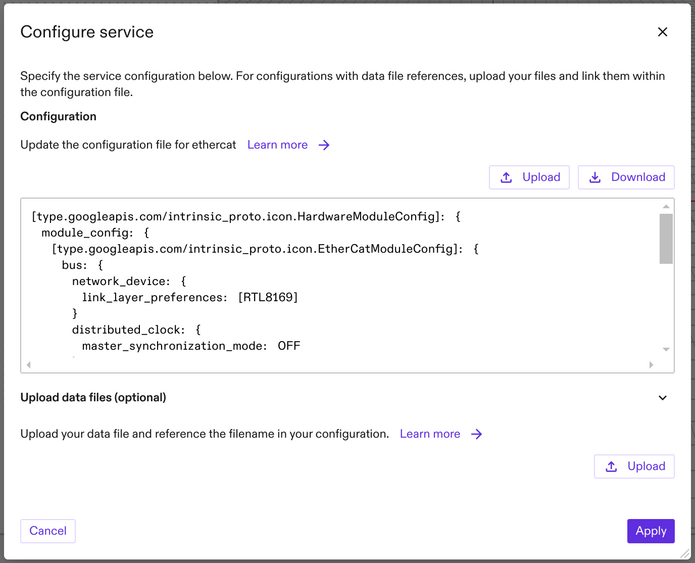
Configuration consists of the following steps:
- Create an ENI file using EC-Engineer-Web, or TwinCat .
- Upload the ENI file.
- Write the Textproto config of the module.
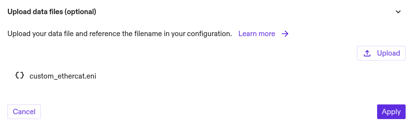
Look at these example configurations if you want to see some working configurations. To upload the ENI file select Upload under Upload data files and choose the file you created above. Once the file has been uploaded and conformity checks have passed, its name will appear in the dialog (custom_ethercat.eni in this example).
The next sections walk you through updating the Textproto configuration for the connected hardware. Choose the sections that match your hardware.
Once the configuration is complete, select Apply. This will check the configuration and apply it.
EtherCAT Bus configuration (required)
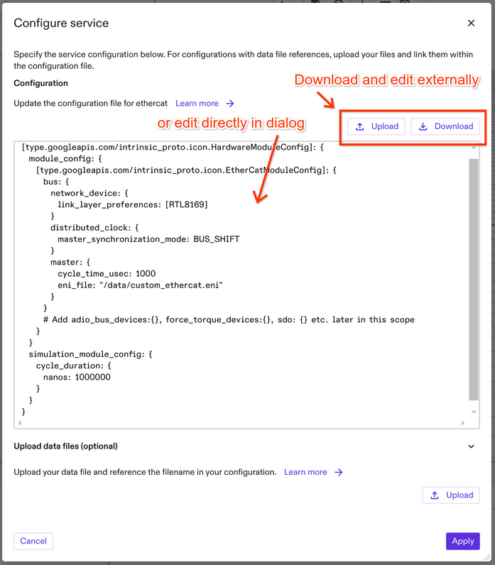
While it is possible to edit the configuration in the dialog, we recommend to download the configuration file and edit it in the editor of your choice. This way, you have a backup in case an invalid configuration gets rejected and find-and-replace functionality is often helpful for larger configurations.
For configuring the bus, the module configuration offers a dedicated bus section.
Find or create the configuration field eni_file under bus.main_device and add the name of the ENI file you just uploaded, prefixed with the path /data (i.e. /data/custom_ethercat.eni).
Next, set bus.main_device.cycle_time_usec to the desired cycle time in microseconds. Note, that this value needs to match the cycle time configured for the realtime control framework service.
Flowstate supports EtherCAT network adapters equipped with specific Realtek or Intel chipsets through so called link layers. To configure the link layer, use the bus.network_device.link_layer_preferences parameter. This parameter expects a list of preferred link layers. Flowstate will attempt to establish a connection using each link layer in the specified order until successful.
Supported link layers:
RTL8169for Realtek devices with the RTL8169 chipsetINTEL_GBEfor Intel-based network devices.
Also, view approved industrial PCs for the list of supported network interfaces for EtherCAT.
To configure the module with both RTL8169 and INTEL_GBE link layers, specify [RTL8169, INTEL_GBE] as the link_layer_preferences list. This may slightly increase the startup time.
The EtherCAT feature distributed clock is enabled by default, unless specifically disabled inside your ENI file. If desired, you can optionally also enable synchronizing the reference clock of the EtherCAT bus to the RTPC internal clock, by setting bus.distributed_clock.main_device_synchronization_mode to BUS_SHIFT.
The cycle_time_usec value must match the cycle time of the hardware module driving the clock. This is usually a robot hardware module. If no hardware module is driving the clock, the control frequency must match the value configured for the realtime control service. If the cycle_time_usec is not correct, the bus might not work properly and fail unpredictably.
The following example configures the bus with the example ENI file from above with a cycle time of 1 millisecond, sets the link layer to RTL8169 and enables BUS_SHIFT Distributed Clock MainDevice (DCM) sync:
[type.googleapis.com/intrinsic_proto.icon.HardwareModuleConfig]: {
  module_config: {
    [type.googleapis.com/intrinsic_proto.icon.EtherCatModuleConfig]: {
      bus: {
        network_device: {
          link_layer_preferences: [RTL8169]
        }
        distributed_clock: {
          main_device_synchronization_mode: BUS_SHIFT
        }
        main_device: {
          cycle_time_usec: 1000
          eni_file: "/data/custom_ethercat.eni"
        }
      }

      # Add adio_bus_devices:{}, force_torque_devices:{}, sdo: {} etc. later in this scope
    }
  }
  simulation_module_config: {
    cycle_duration: {
      nanos: 1000000
    }
  }
}
This EtherCAT hardware module is now functional, but it will not do provide any functionality yet since it's configuration does not contain any devices yet for the real-time control services to communicate with. The next sections describe how to setup inputs, outputs and a force torque sensor.
Adding digital inputs/outputs and analog inputs (optional)
The module configuration offers a dedicated section for digital I/O and analog input configuration: adio_bus_devices. This field supports a list of elements, each of which will be exposed as an ADIO block through the realtime control framework service.
An ADIO block exposes the values of one (for digital I/O) or multiple (for analog input) EtherCAT PDOs (process data object; data that is exchanged in every cycle between EtherCAT MainDevice and SubDevices), called signals. For digital I/O the block consists of the individual bits of the corresponding PDO. Thus, digital I/O blocks must be linked to an EtherCAT PDO of a boolean or unsigned integral type. Consequently, a digital input block for an EtherCAT PDO of type uin32_t will become a block with 32 signals, one signal per bit.
The following example (highlighted section) defines a digital input block:
[type.googleapis.com/intrinsic_proto.icon.HardwareModuleConfig]: {
  module_config: {
    [type.googleapis.com/intrinsic_proto.icon.EtherCatModuleConfig]: {
      bus: {
        network_device: {
          link_layer_preferences: [RTL8169]
        }
        distributed_clock: {
          main_device_synchronization_mode: BUS_SHIFT
        }
        main_device: {
          cycle_time_usec: 1000
          eni_file: "/data/custom_ethercat.eni"
        }
      }
      # Defines a digital input with aliases for individual bits.
      adio_bus_devices: {
        interface_name: "status_ejector_1"
        digital_input_variable: {
          variable_name: "Box 1 (SCTSi-ECT).Receive Data.Status Ejector #1"
          # Optionally define aliases for the individual bits of the PDO.
          bit_index_to_alias: [
            { key: 0 value: "h1_level_reached" },
            { key: 1 value: "h2_level_reached" },
            { key: 2 value: "valve_protection_active" },
            { key: 3 value: "evac_time_exeeds_limit" },
            { key: 4 value: "leakage_rate_exeeds_limit" },
            { key: 5 value: "h1_not_reached" },
            { key: 6 value: "free_flow_vacuum_too_high" },
            { key: 7 value: "manual_mode_active" }
          ]
        }
      }
    }
  }
  simulation_module_config: {
    cycle_duration: {
      nanos: 1000000
    }
  }
}
The interface_name specifies the name under which the module exposes the block towards the realtime control framework service. The presence of digital_input_variable declares this block as a digital input. The signals provided through this block are read from the EtherCAT PDO with variable_name. The name needs to match that of an input PDO as specified in the referenced ENI file and can also be found in e.g. TwinCat when creating the ENI file.
The name Box 1 (SCTSi-ECT).Receive Data.Status Ejector #1 from the example above can be constructed in TwinCat from the device tree. The full names can also be found when looking for the ProcessImage XML-tag inside the ENI file:
...
<ProcessImage>
  <Inputs>
    <ByteSize>1536</ByteSize>
    <Variable>
      <Name>Box 1 (SCTSi-ECT).Receive Data.Status Ejector #1</Name>
      <DataType>USINT</DataType>
      <BitSize>8</BitSize>
      <BitOffs>336</BitOffs>
    </Variable>
    ...
The bit_index_to_alias map optionally allows to provide an alias per bit of the block.
The key is the bit index (LSB first) and the value is the alias.
The indices are zero indexed and need to be smaller than the size of the referenced EtherCAT PDO variable.
The bit_index_to_alias map can also be left empty.
Provided aliases appear in Flowstate's I/O mapping dialog:
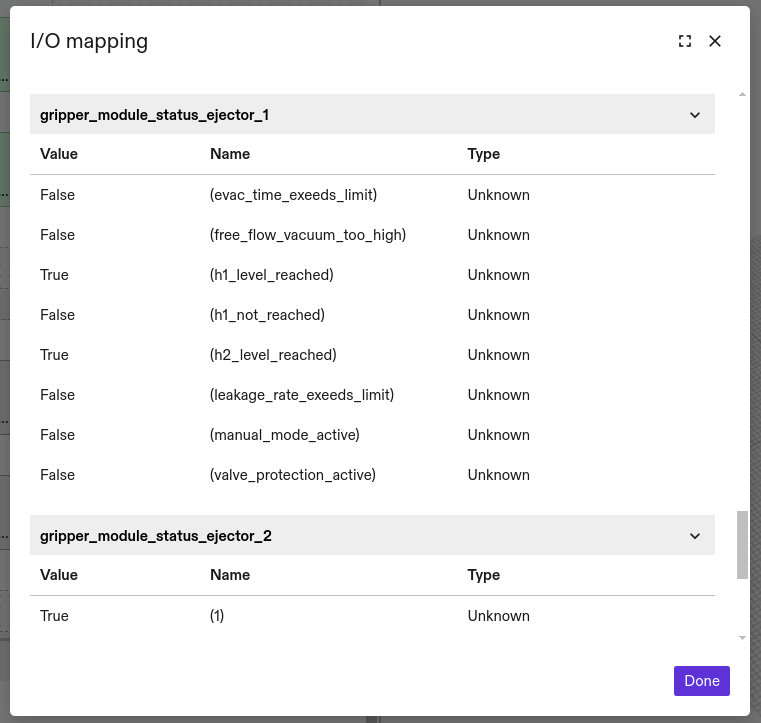
Digital output blocks are defined in a similar way, following the same rules, except that now the variable_name must be an output PDO and the field is a digital_output_variable:
[type.googleapis.com/intrinsic_proto.icon.HardwareModuleConfig]: {
  module_config: {
    [type.googleapis.com/intrinsic_proto.icon.EtherCatModuleConfig]: {
      bus: {
        network_device: {
          link_layer_preferences: [RTL8169]
        }
        distributed_clock: {
          main_device_synchronization_mode: BUS_SHIFT
        }
        main_device: {
          cycle_time_usec: 1000
          eni_file: "/data/custom_ethercat.eni"
        }
      }
      # Defines a digital output with aliases for individual bits.
      adio_bus_devices: {
        interface_name: "control_ejector_1"
        digital_output_variable: {
          variable_name: "Box 1 (SCTSi-ECT).Transmit Data.Control Ejector #1"
          # Optionally define aliases for the individual bits of the PDO.
          bit_index_to_alias: [
            { key: 0 value: "suction" },
            { key: 1 value: "blow_off" }
          ]
        }
      }
    }
  }
  simulation_module_config: {
    cycle_duration: {
      nanos: 1000000
    }
  }
}
In contrast, analog input blocks may consist of various EtherCAT PDOs. The hardware module converts the PDO values to floating point signals and groups them into a single block. The analog_input_variables configuration element supports EtherCAT PDOs of the following types:
- any signed or unsigned integral type
- boolean (where
truebecomes 1 andfalse0) - float
- double
For analog inputs the configuration may look like this:
[type.googleapis.com/intrinsic_proto.icon.HardwareModuleConfig]: {
  module_config: {
    [type.googleapis.com/intrinsic_proto.icon.EtherCatModuleConfig]: {
      bus: {
        network_device: {
          link_layer_preferences: [RTL8169]
        }
        distributed_clock: {
          main_device_synchronization_mode: BUS_SHIFT
        }
        main_device: {
          cycle_time_usec: 1000
          eni_file: "/data/custom_ethercat.eni"
        }
      }
      # Defines an analog input with aliases for each individual variable.
      adio_bus_devices: {
        interface_name: "analog_inputs"
        analog_input_variables: {
          variables: [
            {
              alias: "total_air_consumption"
              variable_name: "Box 1 (SCTSi-ECT).Receive Data.Total Air Consumption"
            },
            {
              alias: "device_status"
              variable_name: "Box 1 (SCTSi-ECT).Receive Data.Device Status"
            }
          ]
        }
      }
    }
  }
  simulation_module_config: {
    cycle_duration: {
      nanos: 1000000
    }
  }
}
As with digital I/Os the aliases are optional. Since each signal of an analog input block is its own EtherCAT input PDO, the alias (if provided) is now provided jointly with each variable_name.
Since adio_bus_devices is a list, you can add an arbitrary number of adio_bus_devices entries for an arbitrary combination of digital/analog inputs/outputs.
Adding Force-torque sensors (optional)
Currently, only ATI Axia 80 or Omega 191 force-torque sensors are supported. You may configure multiple such force-torque sensors under the field force_torque_devices. For each sensor the configuration requires mapping the corresponding EtherCAT input and output PDOs as well as providing the bus_position (with 0 being the first device on the bus) according to the following example:
[type.googleapis.com/intrinsic_proto.icon.HardwareModuleConfig]: {
  module_config: {
    [type.googleapis.com/intrinsic_proto.icon.EtherCatModuleConfig]: {
      bus: {
        network_device: {
          link_layer_preferences: [RTL8169]
        }
        distributed_clock: {
          main_device_synchronization_mode: BUS_SHIFT
        }
        main_device: {
          cycle_time_usec: 1000
          eni_file: "/data/custom_ethercat.eni"
        }
      }
      # Defines an ATI force-torque device.
      force_torque_devices: {
        bus_position: 0
        input_f_x: "Term 1 (ATI Axia F/T Sensor).Reading Data.Fx/Gage0"
        input_f_y: "Term 1 (ATI Axia F/T Sensor).Reading Data.Fy/Gage1"
        input_f_z: "Term 1 (ATI Axia F/T Sensor).Reading Data.Fz/Gage2"
        input_t_x: "Term 1 (ATI Axia F/T Sensor).Reading Data.Tx/Gage3"
        input_t_y: "Term 1 (ATI Axia F/T Sensor).Reading Data.Ty/Gage4"
        input_t_z: "Term 1 (ATI Axia F/T Sensor).Reading Data.Tz/Gage5"
        status_code: "Term 1 (ATI Axia F/T Sensor).Reading Data.Status Code"
        sample_counter: "Term 1 (ATI Axia F/T Sensor).Reading Data.Sample Counter"
        control_codes: [
          "Term 1 (ATI Axia F/T Sensor).Control Codes.Control 1",
          "Term 1 (ATI Axia F/T Sensor).Control Codes.Control 2"
        ]
      }
    }
  }
  simulation_module_config: {
    cycle_duration: {
      nanos: 1000000
    }
  }
}
The full names can be found in the ENI file in the ProcessImage XML-tag in case they do not match the names above.
In this example, the sensor is the first device on the bus (bus_position: 0, see first column of Bus Status UI), thus directly connected to the RTPC. The EtherCAT input PDOs representing the sensor wrench are mapped to the corresponding input_... fields. The additional fields status_code, sample_counter and control_codes are used to monitor and configure the device in operation. control_codes expects the sensor control code PDOs (Object 0x7010) in subindex order.
Step 4: Adding geometric objects
While the EtherCAT hardware module will only communicate with the hardware, in some cases it's advised to also have a physical representation of the hardware in Flowstate as a SceneObject.
This is the case, i.e. if the hardware is mounted to a robot arm and thus becomes part of the kinematic chain (like a force-torque sensor or digital I/O gripper) or if it should be considered for collision checks.
You might be able to find your hardware in the assets catalog. Alternatively, you can also follow the tutorial to add a SceneObject for hardware that is not in the catalog.
In both cases, make sure that the SceneObject is reparented to the correct location in the tree under the Scene tab. For a gripper or force-torque sensor this typically means that it has to be reparented to the robot flange coordinate frame. You find instructions for reparenting in the tutorial about force-torque sensors.
Step 5: Configuring the realtime control framework service
Once the module is configured and any potential SceneObjects are available, follow the steps to configure the realtime control framework service. The auto-configuration will find the configured IOs and the force-torque sensors of the HWM to create the necessary realtime control service configuration.
Additional information
Working with multiple EtherCAT networks
Working with multiple EtherCAT networks is often required to meet system standards. For example, separating cell-control hardware from operational hardware is a necessary practice when setting up and configuring interaction with cell safety systems. For this, your IPC must be equipped with multiple EtherCAT-capable network devices.
For this setup, each EtherCAT bus must be configured with a dedicated instance of the EtherCAT hardware module. One module would be dedicated to cell-control hardware (like digital I/O for the safety system), and another would handle operational hardware (like force-torque sensors).
By default, the EtherCAT hardware module connects to the first EtherCAT-capable network device it detects. You can control this behavior using the bus.network_device.nic_slot parameter. This parameter defaults to 1, selecting the first detected device. To use a different network device, you can change this value. For example, setting nic_slot to 2 will instruct the module to use the second detected EtherCAT-capable network device. If the specified device is not available, the module will report an error.
The following example shows a minimal module configuration that uses the second nic_slot.
[type.googleapis.com/intrinsic_proto.icon.HardwareModuleConfig]: {
  module_config: {
    [type.googleapis.com/intrinsic_proto.icon.EtherCatModuleConfig]: {
      bus: {
        network_device: {
          link_layer_preferences: [RTL8169]
          nic_slot: 2 # or PCI address like 0x01010203 (see below)
        }
        distributed_clock: {
          main_device_synchronization_mode: BUS_SHIFT
        }
        main_device: {
          cycle_time_usec: 1000
        }
      }

      # Add adio_bus_devices:{}, force_torque_devices:{}, sdo: {} etc. later in this scope
    }
  }
  simulation_module_config: {
    cycle_duration: {
      nanos: 1000000
    }
  }
}
While using nic_slot is convenient, it relies on the order in which network devices are detected by the system. This order may rarely change due to kernel-internal behavior after an update, making the configuration less robust. For a more reliable and stable configuration, you can bind an EtherCAT hardware module directly to the PCI address of a specific network device. This ensures that the module always connects to the correct device, regardless of detection order.
PCI addresses typically follow a format like 0000:01:02.3, where 01 is the bus number (bb), 02 is the device number (dd), and 03 is the function number (ff). To use this in the module configuration, you need to convert it to a specific hexadecimal format: 0x01bbddff. For example, to bind to the PCI address above, you would convert the bus number 01, device number 02, and function number 03 into the hexadecimal value 0x01010203. This value can then be used in the module's network device configuration.
Preconfigured force-torque sensor setup
The simplified setup for the two supported force-torque sensors consists of the following 3 steps:
- Configure the RTPC's network interface
- Add the ATI Axia or Omega F/T Hardware Module
- Configure the realtime control framework service
Step 1: Configuring the RTPC's network interface
Please follow the Connect an industrial PC guide to connect the RTPC to the force-torque sensor.
Step 2: Adding the ATI Axia or Omega F/T Hardware Module
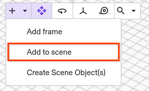
The hardware modules for both sensors are available through the catalog. Select Add to scene to open the corresponding dialog.
Search for any of the following names to find and add the corresponding hardware module:
| Sensor | Name | ID |
|---|---|---|
| ATI Axia 80 | ATI Axia F/T Hardware Module with Simulation | ecat_ft_hal_module_without_adapters_with_sim |
| ATI Omega 191 | ATI Omega F/T Hardware Module | ecat_ati_omega_hal_module |
The next dialog window asks for a name. Select a name of your choice, i.e. ati_module and proceed. Once it is deployed, you find the module in the Services tab on the right. Note, that you might have to switch the tabs for the view to be updated.
Both modules come with a geometry, which needs to be reparented to the robot flange coordinate frame or – in the presence of adapter plates – to any child frame of that flange.
Step 3: Configuring the realtime control framework service
Please read through Configure the realtime control service first. The following configuration lets the realtime control framework service interact with a UR robot and an ATI force-torque sensor (highlighted sections). If you've been led here from the tutorial about force-torque sensors, you should be able to directly apply the highlighted parts of the configuration below.
[type.googleapis.com/intrinsic_proto.icon.IconMainConfig] {
  control_frequency_hz: 500
  hardware_module_read_write_timeout_seconds: 1
  services {
    kinematics_from_world_service: true
    assembly_from_world_service: true
    world_service_from_grpc { world_id: "world" }
  }
  realtime_control_config {
    safety_hardware_interface: { module_name: "ur_module" interface_name: "safety_status" }
    parts_by_name {
      key: "arm"
      value: {
        part_type_name: "HalArmPart"
        safety_action_type_name: "intrinsic.stop"
        hardware_resource_name: "robot"
        config: {
          [type.googleapis.com/intrinsic_proto.icon.HalArmPartConfig] {
            joint_position_command: { module_name: "ur_module" interface_name: "joint_position_command" }
            joint_position_state: { module_name: "ur_module" interface_name: "joint_position_state" }
            joint_velocity_state: { module_name: "ur_module" interface_name: "joint_velocity_state" }
            payload_command: { module_name: "ur_module" interface_name: "payload_command" }
            payload_state: { module_name: "ur_module" interface_name: "payload_state" }
            linear_joint_acceleration_filter_config {
              joint_position_process_noise: 0.001
              joint_velocity_process_noise: 0.001
              joint_acceleration_process_noise: 0.5
              joint_jerk_process_noise: 1250.0
              joint_position_measurement_noise: 1.0E-4
              joint_velocity_measurement_noise: 0.001
              dare_settings {
                max_iterations: 3000
              }
            }
          }
        }
      }
    }
    parts_by_name {
      key: "ft_sensor"
      value: {
        part_type_name: "HalForceTorqueSensorPart"
        safety_action_type_name: "intrinsic.empty"
        config: {
          [type.googleapis.com/intrinsic_proto.icon.HalForceTorqueSensorPartConfig] {
            force_torque_state: { module_name: "axia_hal_module" interface_name: "force_torque_status" }
            force_torque_command: { module_name: "axia_hal_module" interface_name: "force_torque_command" }
            joint_position_state: { module_name: "ur_module" interface_name: "joint_position_state" }
            joint_velocity_state: { module_name: "ur_module" interface_name: "joint_velocity_state" }
            world_robot_collection_name: "robot"
            estimate_post_sensor_dynamic_load: false
            target_link_name: "wrist_3_link"
            ft_sensor_link_name: "AtiForceTorqueSensor"
            support_mass: 1.4
            ft_t_cog: 0
            ft_t_cog: 0
            ft_t_cog: 0.03
            force_control_settings: {
              excessive_force_threshold: 50.0
              excessive_torque_threshold: 50.0
              virtual_translational_inertia: 10.0
              virtual_rotational_inertia: 10.0
              sensed_wrench_deadband: { x: 0.2 y: 0.2 z: 0.5 rx: 0.05 ry: 0.05 rz: 0.05 }
            }
          }
        }
      }
    }
  }

  hardware_module_names: ["ur_module", "axia_hal_module"]
  hardware_module_that_drives_clock: "ur_module"
  main_loop_realtime_priority: true
}
The realtime control framework service compensates for gravity and motion of the force-torque sensor. Thus, it needs to know the geometry and the state of the robot arm. For the geometry, specify the name of the Scene Object that holds the robot geometry under world_robot_collection_name, i.e. robot in the example above. For the state of the robot arm, set the name of the robot hardware module for joint_position_state and joint_velocity_state, i.e. ur_module in this example. Finally, add the name of the force-torque sensor hardware module (axia_hal_module) to the list of hardware_module_names.
The name of a hardware module is typically the one defined in the Scene. In some cases though, the module may overwrite this name using the name: field in the hardware module configuration with a fixed name (axia_hal_module in this case).
Service Data Objects (SDO) configuration
Acyclic data in the form of SDOs can be written, or read in a non realtime context by suppling a intrinsic_proto.ecat.SdoConfig in the module configuration.
sdo: {
  sdo_writes: [
    {
      sdo_variable: {
        # Values can be declared in any format supported by protobuf. Using hex for simplicity.
        index: 0x6061
        sub_index: 0x00
        bus_position: 1
      }
      value: {
        int8_value: 8
      }
    }
  ]
  sdo_reads: [
    {
      sdo_variable:  {
        index:  0x6041
        sub_index: 0x0
        bus_position: 0
      }
      type:  UINT16_SDO_TYPE
      alias:  "drive_1_status_word" # Required if also defined as analog input by using sdo_export_type SDO_EXPORT_TYPE_ANALOG_INPUT*
      interpretations_of_values: [
        {
          key: "Ready to switch on"
          value: {
            patterns: { expected_value: 1 signal_mask: 1 }
          }
        },
        {
          key: "Switched on"
          value: {
            patterns: { expected_value: 2 signal_mask: 2 }
          }
        },
        {
          key: "Operation enabled"
          value: {
            patterns: { expected_value: 4 signal_mask: 4 }
          }
        },
        {
          key: "Fault"
          value: {
            patterns: { expected_value: 8 signal_mask: 8 }
          }
        },
        {
          key: "Voltage enabled"
          value: {
            patterns: { expected_value: 16 signal_mask: 16 }
          }
        },
        {
          key: "Quick stop"
          value: {
            patterns: { expected_value: 32 signal_mask: 32 }
          }
        },
        {
          key: "Switch on disabled"
          value: {
            patterns: { expected_value: 64 signal_mask: 64 }
          }
        }
      ]
    }
  ]
  # Additionally logs the SDO values to the k8s cluster logs.
  sdo_export_type: SDO_EXPORT_TYPE_PUBSUB_AND_LOG
}
Writing SDO values
SDO values are written during the initialization phase of the bus devices.
The sdo_writes example above sets the value 8 of type INT8 for the device on bus position 1 with index 0x6061 and subindex 0x00.
Reading SDO values
The sdo_reads example above cyclically logs the value as read from the device and publishes it so that it can be viewed in the frontend.
The expected value is of type UINT16 for the device on bus position 0 with index 0x6041 and subindex 0x0.
A wrong type is likely to lead to a runtime error, which will be visible in the cluster logs.
The interpretations_of_values map allows providing human readable interpretations of the value. This allows providing specific interpretations based on boolean logic. An interpretation is shown, if the bitwise-OR between the read SDO value and the signal_mask equals the provided signal_value (i.e. if read_sdo_value & signal_mask == expected_value equals true).
In the example above the interpretations_of_values decodes individual status word bits of a CiA/DS402 device into human readable descriptions of the device state.
The sdo_export_type defaults to publishing only. You make the SDO values and their interpretations accessible through the frontend by either of the following ways:
- Select the module under Services and then select Show SDO Export in the Settings tab on the left side of the Flowstate window.
- Select File | Equipment Manager and in there press Open SDO Export.
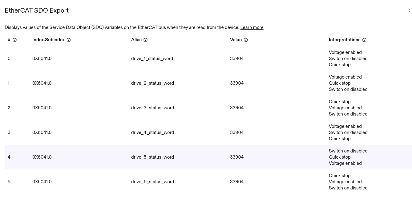
The list is automatically refreshed with every published set of messages and is empty until the first message arrives.
The export behavior can be changed by setting sdo_export_type to either of the following values:
SDO_EXPORT_TYPE_DEFAULT(default): SDO values are only visible through the frontend (via Pub/Sub).SDO_EXPORT_TYPE_LOG: SDO values are only visible in the cluster logs.SDO_EXPORT_TYPE_PUBSUB_AND_LOG: SDO values are visible both, through the frontend (via Pub/Sub) and through the cluster logs.SDO_EXPORT_TYPE_NONE: SDO values are not shown at all.SDO_EXPORT_TYPE_ANALOG_INPUT: SDO values are provided as an analog input hardware interface to ICON. Requiresaliasto be set.SDO_EXPORT_TYPE_ANALOG_INPUT_AND_PUBSUB: SDO values are provided as an analog input hardware interface to ICON and are visible through the frontend (via Pub/Sub). Requiresaliasto be set.SDO_EXPORT_TYPE_ANALOG_INPUT_AND_PUBSUB_AND_LOG: SDO values are provided as an analog input hardware interface to ICON, are visible through the frontend (via Pub/Sub) and in the cluster logs. Requiresaliasto be set.
When using any of the ANALOG_INPUT export types, setting the alias field is required, since it will be used as the interface name and analog input block name. For example:
sdo: {

  # sdo_writes, ...

  sdo_reads: [
    {
      sdo_variable:  {
        index:  0x6041
        sub_index: 0x0
        bus_position: 0
      }
      type:  UINT16_SDO_TYPE
      alias:  "drive_1_status_word" # Required due to `SDO_EXPORT_TYPE_ANALOG_INPUT`
    }
  ]
  # Provides the SDO values as an analog input hardware interface.
  sdo_export_type: SDO_EXPORT_TYPE_ANALOG_INPUT
}
A corresponding HalADIOPartConfg for ICON that accesses this SDO variable looks like this:
[type.googleapis.com/intrinsic_proto.icon.HalADIOPartConfig] {
  analog_inputs: [
    { interface: { module_name: "ethercat_module" interface_name: "drive_1_status_word" } }

     # other analog input interfaces, ...
  ]
  # digital inputs or outputs, ...
}
Testing and error reporting
It may take a couple of seconds until configuration changes are applied. Consult the Diagnosis and troubleshooting site in case of problems.
Example configurations
The following table contains a list of ready to use ENIs with corresponding module Textproto configurations. Please remember to also add and reparent the force-torque sensor Scene Object.
| Bus Topology | Configuration Files | F/T Sensor Scene Object ID |
|---|---|---|
| Module: single_ati_axia_ft.textproto | ai.intrinsic.axia80_m20_updated |
| Module: single_ati_omega_ft.textproto | ai.intrinsic.fte_ecat_omega191_ip65 |
| Module: ep2338_and_ati_axia_ft.textproto | ai.intrinsic.axia80_m20_updated |
| ai.intrinsic.axia80_m20_updated | |
| ai.intrinsic.axia80_m20_updated |