ENI generation and diagnosis with EC-Engineer Web
EC-Engineer Web is an EtherCAT configuration and introspection/debugging tool that can run as a service on an Intrinsic cluster.
It supports online and offline configuration. Online means that EC-Engineer Web can connect to an existing bus and devices. Offline means that the bus is not available.
The online configuration can be performed in a standalone fashion, meaning without an ethercat hardware module, or linked to an EtherCAT hardware module.
Standalone is recommended when starting with an empty application, linked when the solution already contains an EtherCAT hardware module.
EC-Engineer Web automatically disables after 8 hours to free up one license and you will lose unsaved data.
You can re-enable EC-Engineer Web using the Service Manager.
It automatically restores imported ESI files and you can re-open (File | Open) projects saved on the server.
If you remove, or restart (instead of disable/enable), you lose all data stored inside EC-Engineer Web.
Therefore, download you project and ENI files.
Offical Documentation
Please consult the official documentation for topics not covered here.
- Official documentation.
- EC-Engineer non Web Video Tutorials (looks different from EC-Engineer Web but the steps are similar)
Online and offline configuration
You have the choice to perform an online or an offline configuration:
-
With online configuration, EC-Engineer Web scans the EtherCAT bus for devices and automatically derives the bus topology and (for some devices) even the terminal configuration, both of which can later be changed and extended manually. For this to work, EC-Engineer Web must be started on a physical cluster that is connected to the EtherCAT bus.
-
With offline configuration, you manually create the bus topology and (if applicable) the terminal configuration of certain devices.
Use the following table to decide which configuration method to follow in your scenario.
| Criteria | Online configuration | Offline configuration |
|---|---|---|
| Physical connection | Requires the machine running EC-Engineer Web to have a supported EtherCAT network device and be physically connected to the bus | Can be performed remotely, even with EC-Engineer Web running in a virtual machine |
| ESI requirements | Users are recommended to have compatible ESI files for all bus devices available | Users are required to have compatible ESI files for all bus devices available |
| Bus topology | Topology and configuration are automatically derived | Topology and configuration need to be defined manually |
| Validation | Allows validating that bus devices are operational | Does not offer any validation |
If you can physically connect to the hardware, online configuration may be more convenient. Note that it does not warn about some wiring errors (i.e. wrong device order on the bus).
If you cannot fulfill the higher requirements, or if you want to ensure that your bus topology follows a previously specified design, you should follow offline configuration.
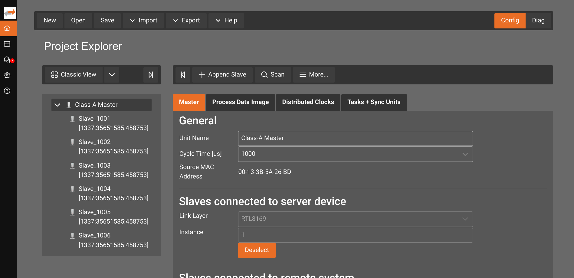
Standalone
EC-Engineer Web can be used without an EtherCAT hardware module in the solution. It includes support for interacting with the bus using the native link layer and can be used for online- and offline configuration.
Since EC-Engineer Web and the EtherCAT hardware module require access to the same EtherCAT network interface (managed by Kubernetes), you cannot run instances of both the EtherCAT hardware module and the standalone EC-Engineer Web at the same time. Make sure that only one instance is part of your solution at any time. Otherwise, the second instace will fail to access the EtherCAT network interface.
EC-Engineer Web is available through the assets catalog. Select Add service, then find
EtherCAT EC-Engineer Web (Standalone) and select the one with the ID ai.intrinsic.acontis_ec_engineer_web.
The next dialog window asks for a service name. Select a name of your choice, i.e. ec_engineer and proceed. The service is now being deployed and will be available shortly.
Once it is deployed, you find the service in the Services tab on the right. Note, that you might have to switch the tabs for the view to be updated.
You can continue to:
- Open the EC-Engineer web interface
- Choose
Online Configuration.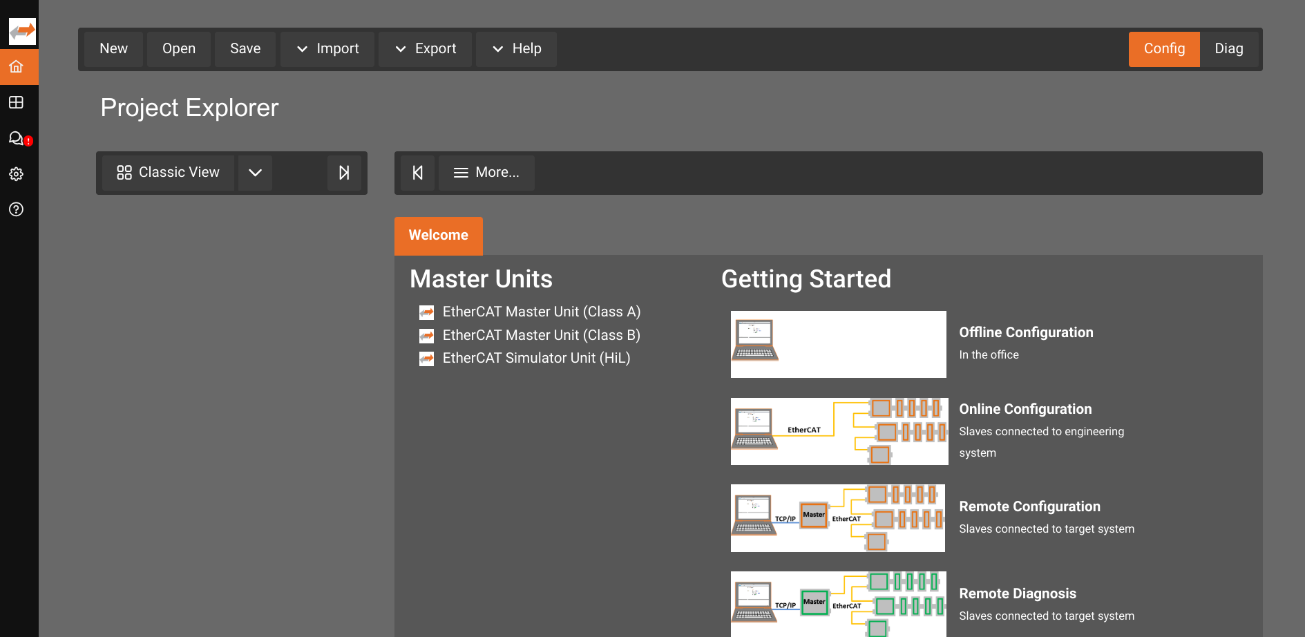
- Select
Class AMaster.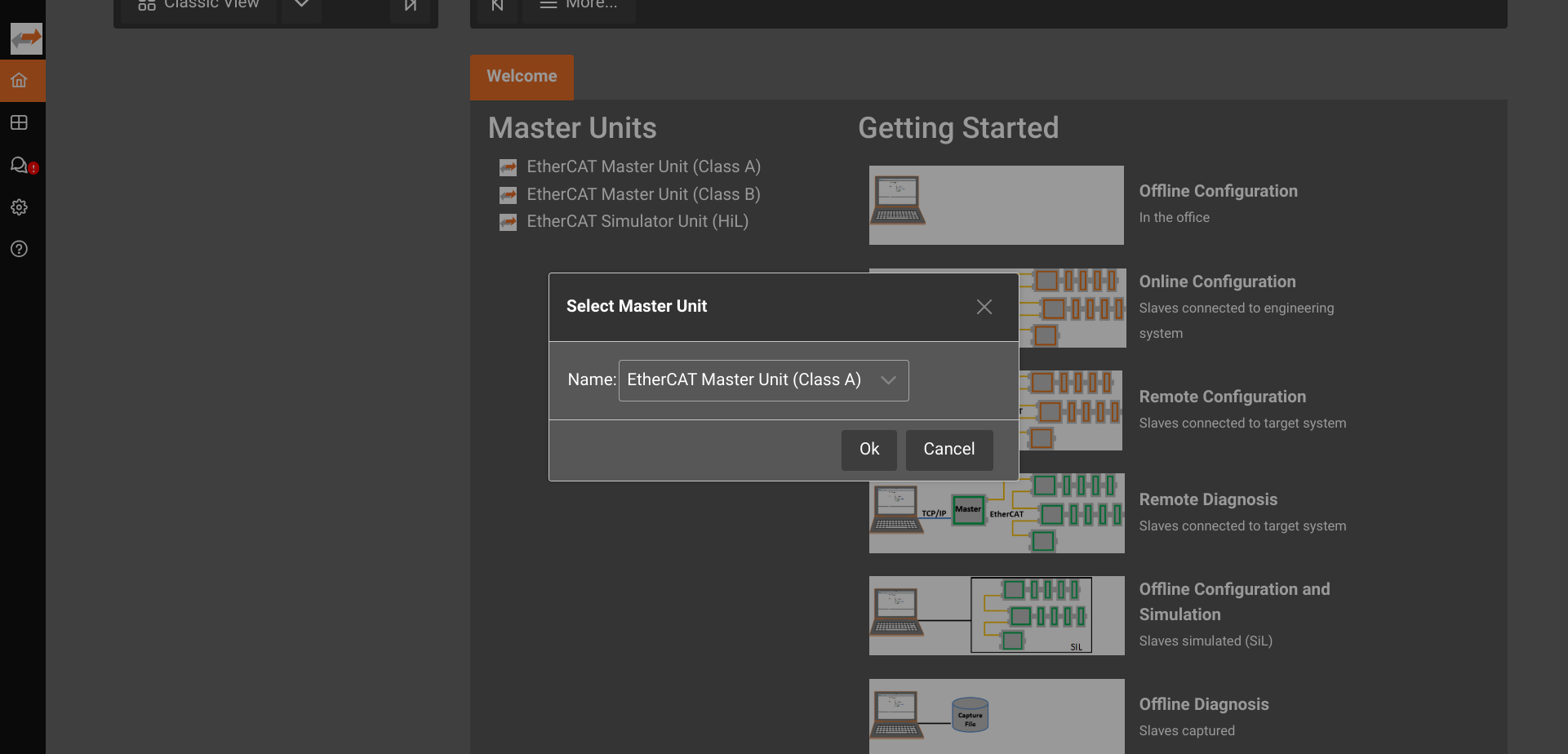
- Select the appropriate Link Layer. Most systems use
RTL8169.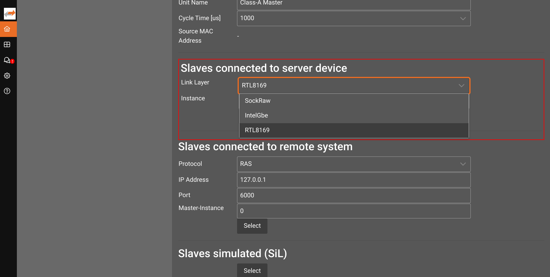
- Select the correct link layer instance. Most systems use
Instance1.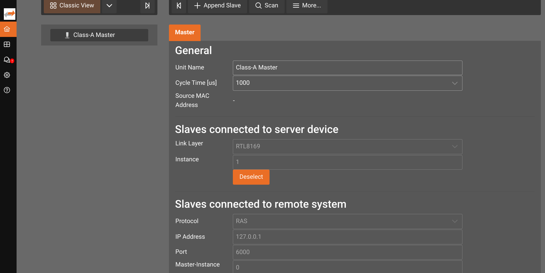
- Continue by
Scaning, or manually configuring the bus.
Linked to EtherCAT hardware module
EC-Engineer Web can connect to a running instance of the EtherCAT hardware module by using the Remote Diagnosis (RAS) interface. This allows using it for online configuration, or the introspection and debugging of a finished solution.
A prerequisite is to enable RAS on the EtherCAT hardware module.
EC-Engineer Web is available through the assets catalog. Select Add service, then find
EtherCAT EC-Engineer Web (linked/RAS) and select the one with the ID ai.intrinsic.acontis_ec_engineer_web_ras.
The next dialog window asks for a service name. Select a name of your choice, i.e. ec_engineer and proceed. The service is now being deployed and will be available shortly.
Once it is deployed, you find the service in the Services tab on the right. Note, that you might have to switch the tabs for the view to be updated.
You can continue to:
- Open the EC-Engineer web interface
- Connect to the EtherCAT hardware module via RAS
- Continue with Remote Online ENI Creation, or Remote Diagnosis by connecting via RAS
Connect to the EtherCAT hardware module via RAS
After you selected either of the workflows Remote Online ENI Creation, or Remote Diagnosis, you need to configure the RAS connection. The connection settings are the same for both remote options.
RAS needs to be enabled on the EtherCAT hardware module.
Follow these steps to connect your EC-Engineer Web to the EtherCAT hardware module:
- Get the IP of the RAS service exposed by the EtherCAT hardware module. The RAS server of the hardware module defaults to port
7241. - Use those connection parameters in the section
SubDevices/Slaves connected to remote systemand pressSelect.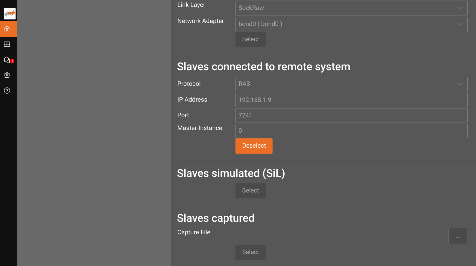
You can check that everything is working by switching to the Diag view.
Remote Online ENI Creation
If the EtherCAT hardware module is already configured with a wrong ENI file, remove the eni_file parameter in addition to enabling RAS.
- Choose
Remote Configuration. - Select
Class AMaster. - Continue by
Scaning, or manually configuring the bus.
Remote Diagnosis
- Choose
Remote Diagnosis. - Select
Class AMaster. - Continue with diagnosing the bus.
Open EC-Engineer Web interface
You can access the web interface in the same way as an HMI Service, by connecting via the Local Network.
Once EC-Engineer Web is started, it will print the URL to its web interface in the Service Manager dialog.
For example when added with the name "ec_engineer", it will print http://xfa.lan:17080/ext/services/ec_engineer/.
The link only works with a trailing slash (/) at the end of the URL.
Some projects also feature a cloud gateway that enables remote access.
To access remotely, replace the domain name of the URL from above and follow this scheme:
https://flowstate.intrinsic.ai/content/projects/**PROJECT**/uis/onprem/clusters/**CLUSTER**/**SUFFIX-FROM-URL-ABOVE**
Configuration / ENI creation
To configure the EtherCAT bus you typically perform the following steps:
- Add required ESI files
- When using online configuration
Scaning the bus. - (optionally) Manually adjust the Process Image.
- Test the configuration.
- Export the ENI file.
- Download the project file.
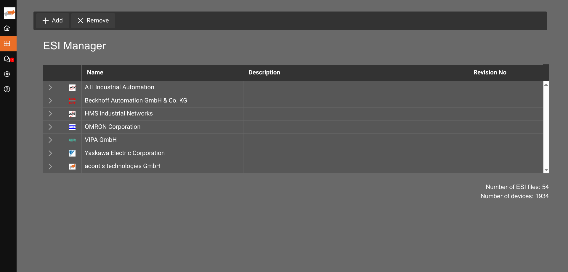
Provide ESI files using Manager
EtherCAT device manufacturers typically provide ESI files (EtherCAT SubDevice Information) for their EtherCAT devices. These files describe the characteristics and capabilities of a device (or family of similar devices) and thus contain information for the EtherCAT MainDevice to enable a reliable communication. ESI files are usually available on the manufacturer website or can be obtained through a support request from the corresponding vendor.
If you have a device without an ESI file, you might still be able to use it based on the information this device publishes through its SII (SubDevice Information Interface). EC-Engineer Web is able to query SII during a bus scan. You need to perform an online configuration.
The EC-Engineer Web service already includes some commonly used ESI files. Add aditional ones using the ESI Manager.
(Optional) Configure the cycle time and synchronization
DS402 drives typically required a correct cycle time and Distributed Clock configuration to work correctly.
When configuring DS402 drives, please set the correct cycle time 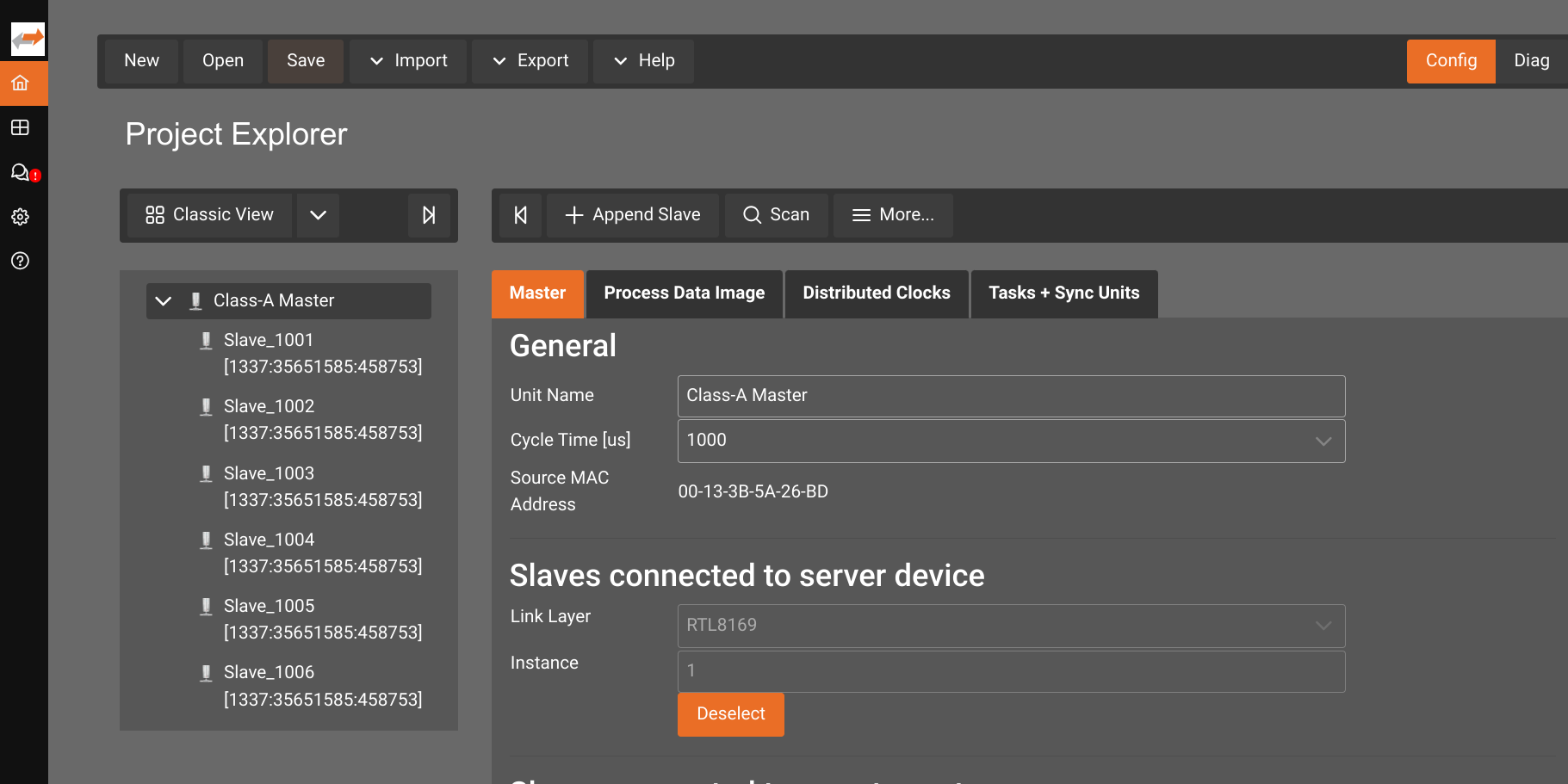 and configure the
 Distributed Clocks to Bus Shift 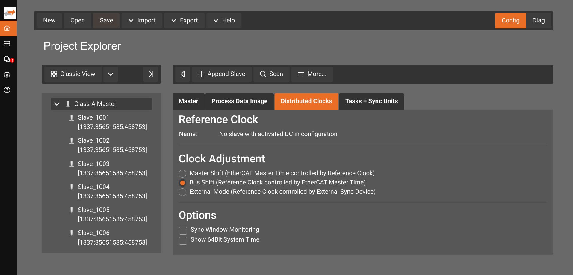
Test and export ENI
When all devices are added and configured, test and export the ENI file.
- Test the configuration
- Switch to the
Diagtab. - Check that all devices can reach the mode
OP.
- Switch to the
- Download the project file using
File | Save, so you don't have to start from scratch when making changes later.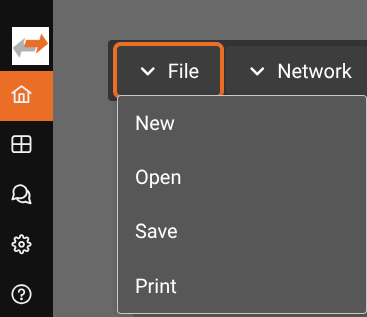
- Export and download the ENI file for use with the EtherCAT hardware module via
Network | Export ENI File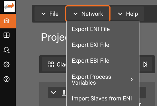
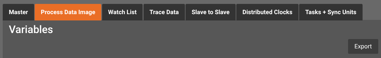
(Optional) Export the Process Data Image (PDO) as CSV
The PDO configuration can be exported as a CSV file.
(Recommended) Print the documentation
The printed (as PDF) documentation contains the bus layout and PDO configuration, which is useful for configuring the EtherCAT hardware module.
Introspection and Debugging
EC-Engineer can be used to introspect the EtherCAT bus while the hardware is being controlled by Flowstate.
Follow the instructions to Link EC-Engineer to an EtherCAT hardware module and choose Remote Diagnosis.
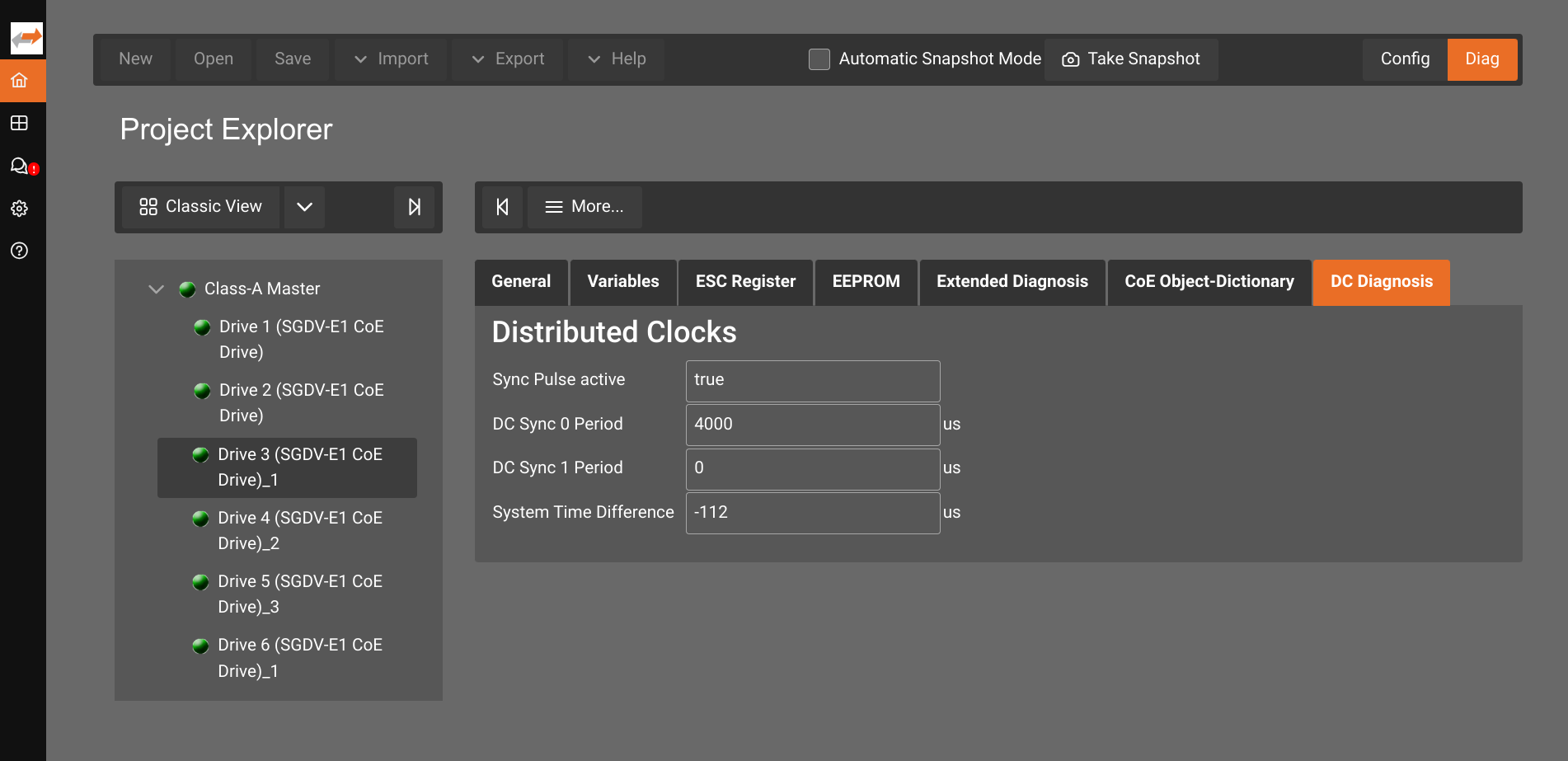
Inspect the state of the distributed clocks
The screenshot shows that the drive is configured for Distributed Clock and also the System Time Difference to the Main device.
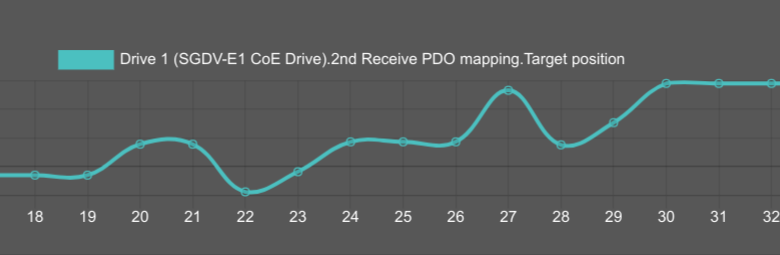
Plot sensor data, or commands
The screenshot shows the commanded target position of a single drive over time.
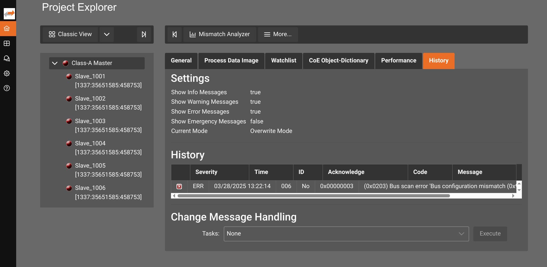
Investigate the history of the bus/main device
The screenshot shows that the Main device could not be started because of a bus configuration mismatch.
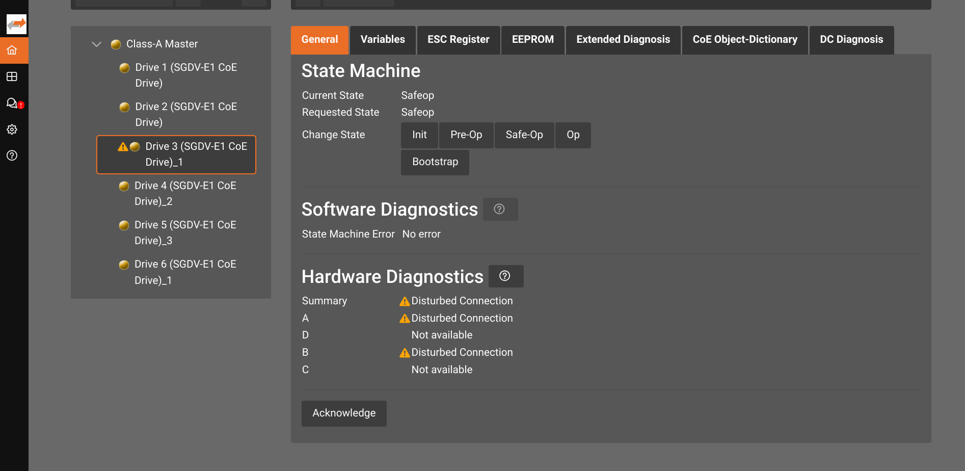
Investigate the StateMachine and hardware diagnosis
The screenshot shows a connection issue for Drive 3.
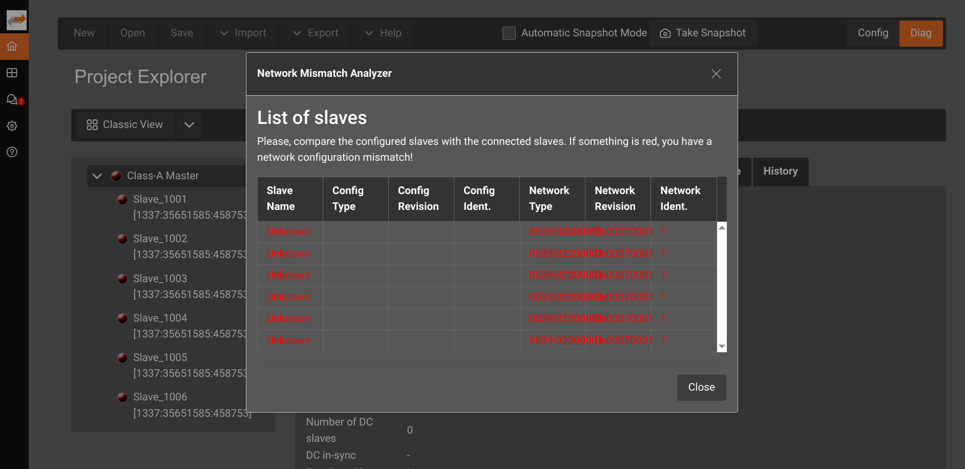
Investigate mismatches between ENI and bus
The screenshot shows the Network Mismatch Analyzer for an ENI that does not match the bus layout.
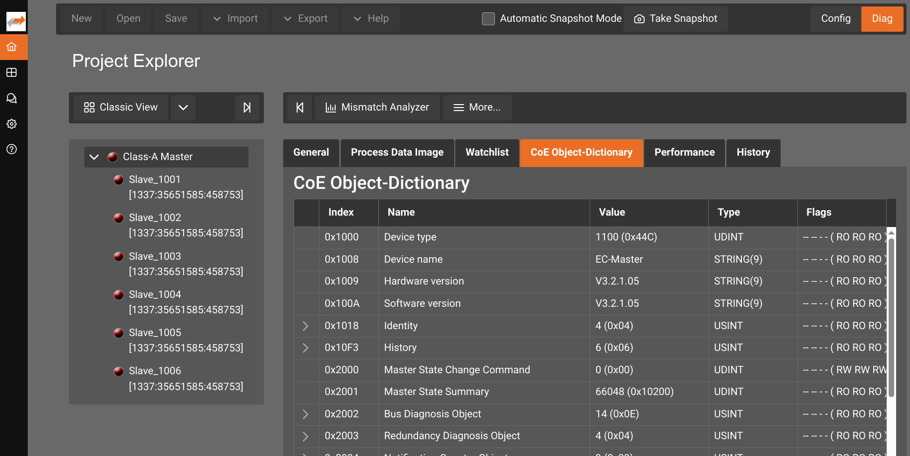
Search and observe the CoE Object-Dictonary
The screenshot shows the CoE Object-Dictonary. It can be used to adjust the process image, or interesting variables for an SDO export.
Inspect an existing ENI file
An existing ENI file can be imported as a project for further modification, or to get an overview of e.g.:
- Expected bus layout
- Distributed Clock settings
- Revision of Slave devices
For this:
- Import required ESI files.
- Add a Master Unit e.g.
EtherCAT Master Unit (Class A) Importthe ENI file.
Troubleshooting
The logs contain relevant information. 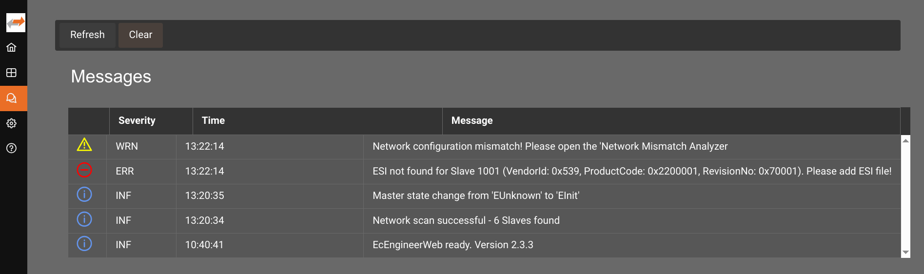
Connection issues
Failed to connect Master-Unit: ERROR: Master core not accessible (ErrCode: 0x9811002E)
Issue can be encountered when scaning the bus, or switching to Diag. Known causes:
- RAS is not enabled in EtherCAT hardware module. Enable RAS.
- Missing EtherCAT hardware module. Use EC-Engineer in standalone mode instead or add an EtherCAT hardware module.
- RAS connection IP / Port mismatch. Check RAS settings.
- Wrong
Master-Instance(the EtherCAT hardware module defaults to0).
Failed to connect Master-Unit: ERROR: Not found (ErrCode: 0x9811000C)
Issue can be encountered when scaning the bus, or switching to Diag. Known causes:
- Using
SubDevices/Slaves connected to server devicewith EC-Engineer in linked mode. Connect to an EtherCAT hardware module via RAS, or use EC-Engineer in standalone mode - Wrong link layer, or instance when using EC-Engineer in standalone mode. Select the correct link layer.
Error: Device not found
Error is shown when Importing an ENI when no Master Unit is defined.
Add an EtherCAT Master Unit (Class A) and retry.
Startup issues
Startup issue can be caused by:
- Issues with the license. Check the Service Manager dialog and container logs.
- Using EC-Engineer Web standalone in parallel to an EtherCAT hardware module.
The error when scheduling the pod is
Insufficient atemsys.acontis.com/ecat-driver. You can either- Use the linked version of EcEngineer
- Remove the EtherCAT hardware module from your solution and use the standalone version.