Perform a reachability analysis
A reachability study can be run in order to check if a robot can reach all the desired positions and can target either a region of the workcell, or a set of individual points. The first version of the reachability tool focuses on IK only reachability.
When a robot is selected the robot's Settings panel displays the Reachability section.
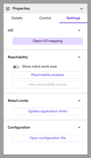
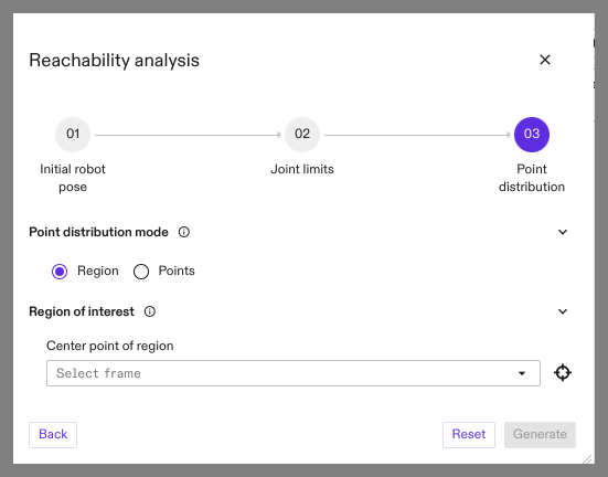
- Click Reachability analysis to open the Reachability Analysis dialog. This dialog allows the user to specify and preview settings used during the reachability analysis.
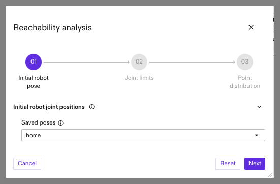
- Select the initial joint positions from which the robot moves when testing reachability. Selection includes the current robot joint positions and any pre-saved poses.
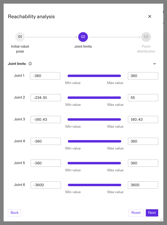
- Optionally, restrict movement of joints by enforcing limits more restrictive than system limits.
-
Point distribution mode defaults to region of interest. In this mode reachability is tested over a set of points within a discrete region of interest centered around a frame. This frame is specified by selecting a Center point of region frame. This selection can be performed either by selecting a frame through the menu, or by clicking the crosshair icon and then selecting a frame in the scene, or scene tree.
-
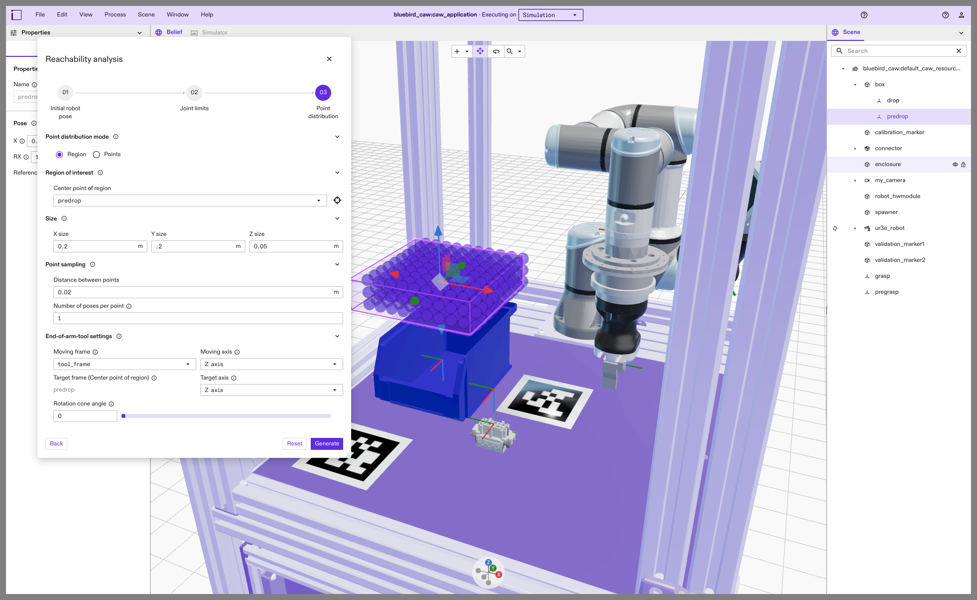
After a frame is selected, the scene shows a preview of the region of interest and displays what locations within the region were sampled.
-
The extents of the region of interest can be specified using the Size section, and the distance between the sample points, in meters, can be specified by Distance between points.
-
Number of poses per point is the number of poses that are sampled for each sample point.
- The End-of-arm-tool settings section allows the user to specify parameters related to the end-of-arm tool.
- Moving frame is the frame used to reach the sample points within the region of interest.
- Target frame is the frame that defines either the target points or region of interest center.
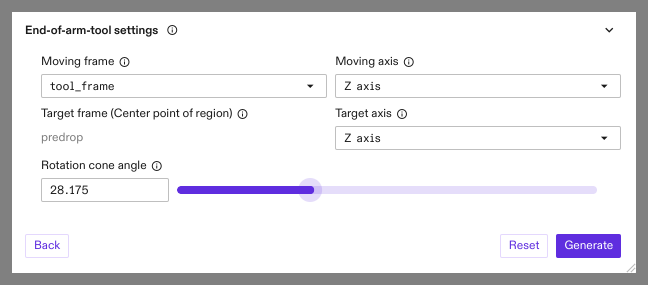
- Moving axis is the axis on the Moving frame that will be used to match the Target axis on the Target frame.
- Target axis is the axis used to constrain the orientation of the EOAT frame. This axis is relative to the selected Target frame.
- Rotation cone angle is the half-angle of rotation cone constraint used to limit the orientation of the EOAT frame. This angle is relative to the specified Rotation cone axis.
When using a single pose, the reachability tool always attempts to match the orientation of the Moving frame with the Target frame. The Target axis and Rotation cone angle settings are only applicable when using more than one pose.
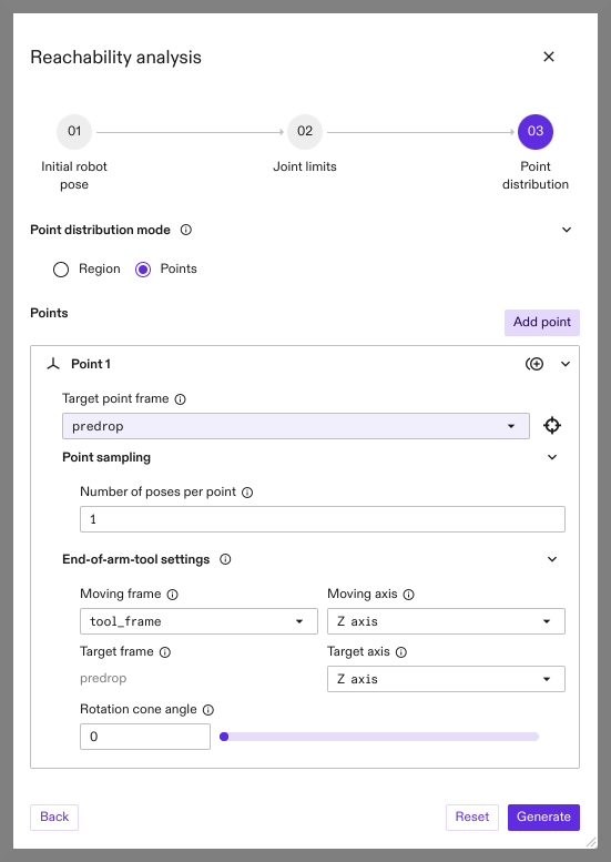
- To perform the reachability study over a specific set of points, click the Points option in the Point distribution mode section. In this mode it's possible to use frames to define a list of independent sampling points within the workcell. When using this mode, End-of-arm-tool-settings can be specified independently for each point. After filling the information for a point, clicking Add point adds a new empty point to the list.
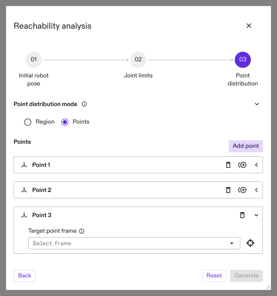
- Parameters for each point can be edited by expanding the corresponding section. Additionally, points can be removed from the list or duplicated by using the icons on the right-hand side of each section.

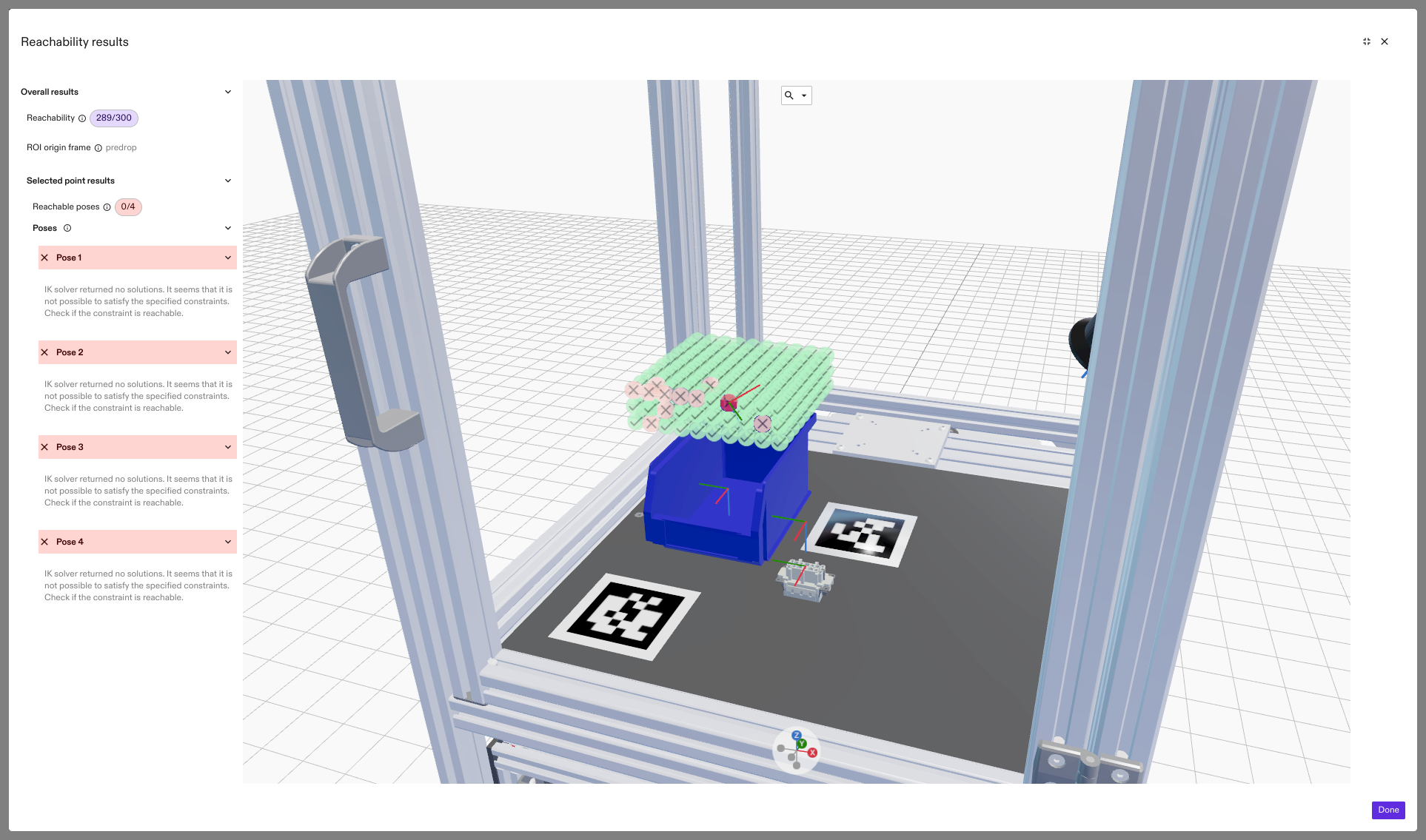
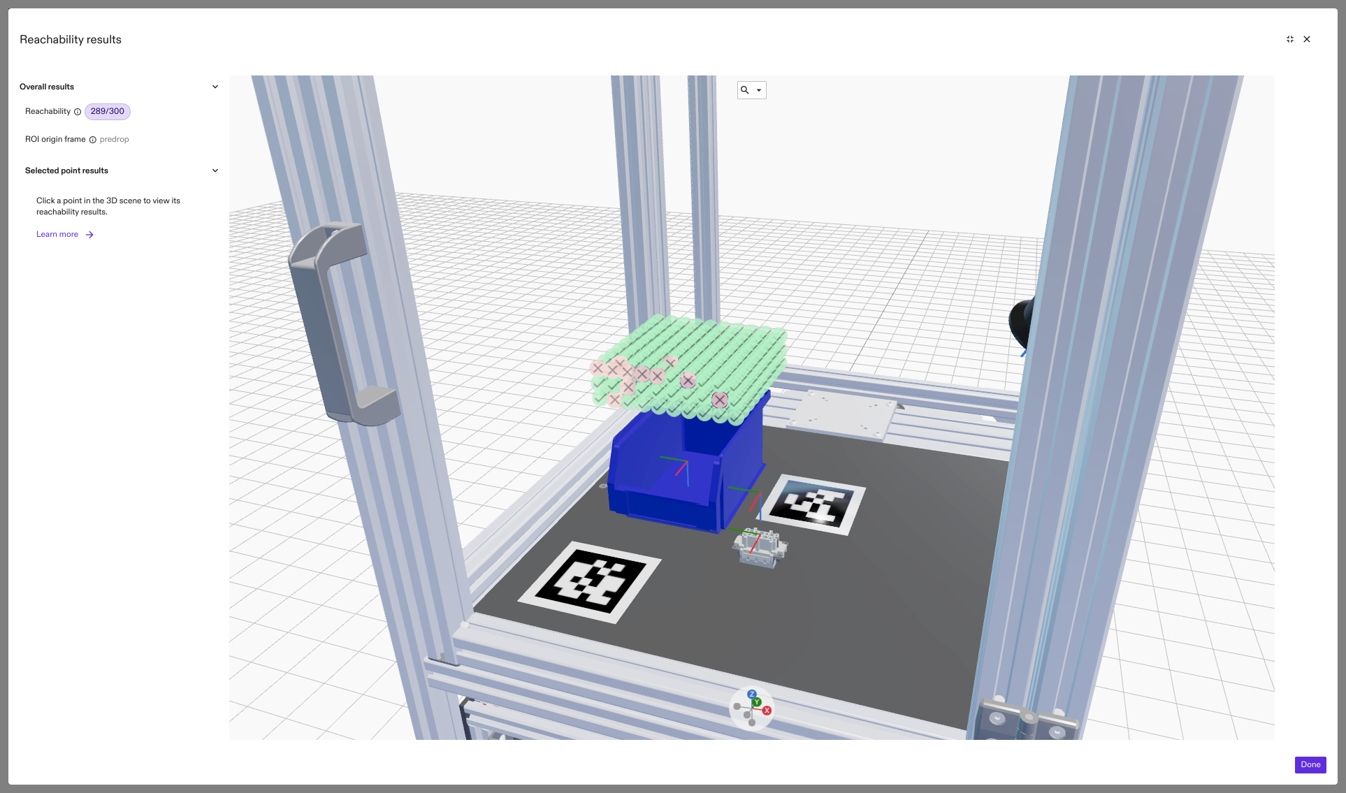
- Clicking Generate runs the reachability study with the selected parameters. After the study is complete the Reachability area of the settings panel for the robot shows the View reachability results button. Clicking this button opens a new dialog displaying the state of the world at the time the study was launched, and a set of icons indicating reachability of each point.
- Clicking on a point icon shows a list of poses that were sampled for the point, as well as a list of successful IK solutions for each pose. The robot-joint positions for each IK solution can be previewed by clicking on the list on the left side. Hovering the mouse over each pose section header shows the pose's orientation in the 3D results scene.
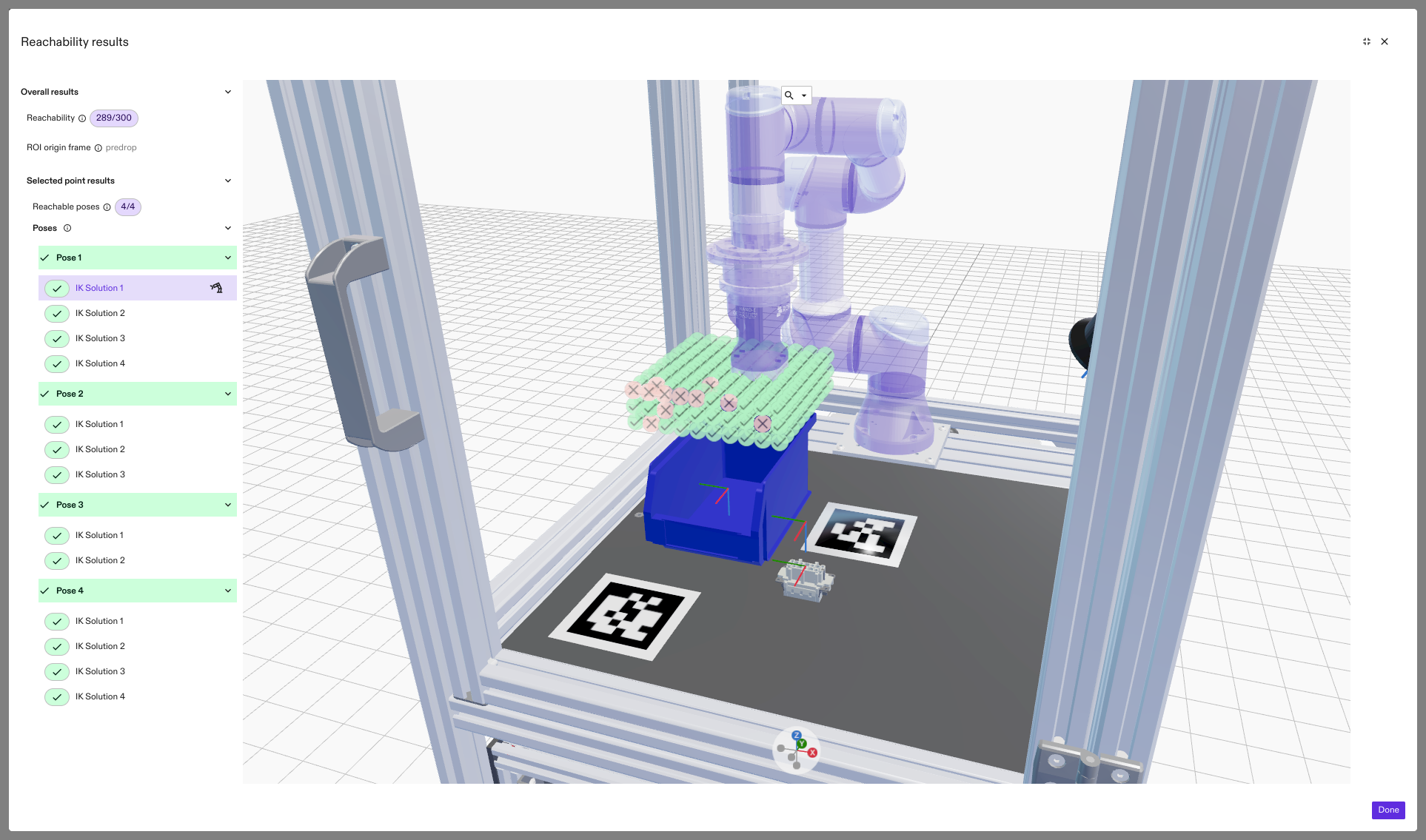
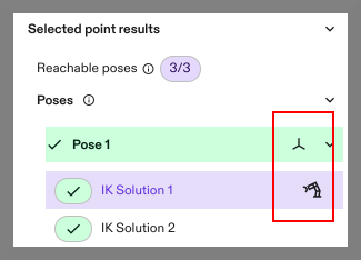
- Clicking the frame icon that appears in each pose header saves the current pose as a frame in your scene. When a specific IK solution is selected, clicking on the robot icon saves the IK solution as a named joint configuration. The named configuration appears in the robot's Control panel after the reachability results dialog is closed.
- Unreachable points are marked with a red icon. Selecting one of these points and the corresponding failed pose, shows a detailed explanation of the failure case, including detailed collision information.